Section 7
ILLUSTRATIONS AND PARTS LIST
41
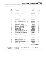
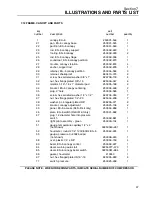
7.10 CONTROL BOX
key
part
number
description
number
quantity
1
Consult factory for starter group, and refer to compressor serial number.
3
bracket, top starter
250039--244
1
4
plate ES--6, access (Ref.)
250034--858
1
5
locknut, conduit 1/2”
847200--050
3
6
nipple, chase 1/2” npt
847815--050
2
7
decal, 3 position switch panel
250039--113
1
8
hose, nylon 1/4”
842215--004
5 ft.
9
valve, solenoid 1/8” 110/120
(I)
250030--164
1
10
box, junction
250026--740
1
11
screw, hex serrated washer 1/4” x 1/2”
829704--050
9
13
lug
849215--004
1
14
nut, hex flanged 1/4”--20
825304--236
9
15
switch, selector 3 position
248168
1
16
elbow, 90
q
m swvl 1/8T x 1/8 NPT
250025--849
2
17
pushbutton, “manual/reset”
02250045--011
1
18
screw, 1/4”--20 x 1/2” long
250030--162
4
19
fastener, suregrip
041516
2
20
nameplate, Sullair 1” x 6”
250035--063
1
21
joint, compression phase 230V, 3PH
250026--615
1
S
phase 3 460V (not shown)
250026--615
3
22
insulator, splice phase 1 230V, 3PH
250006--110
1
S
phase 3, 460V (not shown)
250006--110
3
23
panel, circuit board
250025--863
1
24
Consult factory for starter group, and refer to compressor serial number.
25
transformer
02250045--012
1
26
rivet, pop 1/8” x 3/8”
843102--038
4
27
nameplate, Sullair
02250059--318
1
28
gauge, pressure 0--200# bar/psi
250005--185
1
29
tee, male branch 1/8”
250026--139
1
30
connector, male tube straight 1/8” x 1/4”
250025--858
1
31
plug, hole 1/2”
045689
1
(Continued on page 43)
(I)
For maintenance on solenoid valve no. 250030--164, order repair kit no. 250038--849, and
replacement coil no. 250035--292.
PLEASE NOTE: WHEN ORDERING PARTS, INDICATE SERIAL NUMBER OF COMPRESSOR
Summary of Contents for ES-6 series
Page 6: ...NOTES...
Page 30: ...Section 7 ILLUSTRATIONS AND PARTS LIST 24 ES 6 COMPRESSOR ASSEMBLY EXPLODED VIEW 5 5 AND 7 5KW...
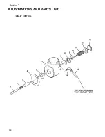
Page 32: ...Section 7 ILLUSTRATIONS AND PARTS LIST 26 7 3 FLUID MANAGEMENT SYSTEM...
Page 34: ...Section 7 ILLUSTRATIONS AND PARTS LIST 28 7 4 INLET FILTER...
Page 36: ...Section 7 ILLUSTRATIONS AND PARTS LIST 30 7 5 SEAL AND DRIVE GEAR...
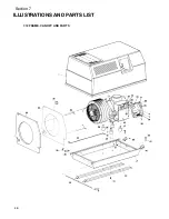
Page 38: ...Section 7 ILLUSTRATIONS AND PARTS LIST 32 7 6 MOTOR HOUSING AND PARTS 7 5 10HP 5 5 7 5KW ONLY...
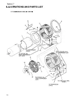
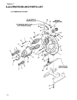
Page 42: ...Section 7 ILLUSTRATIONS AND PARTS LIST 36 7 8 COMPRESSOR SYSTEM...
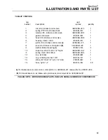
Page 44: ...Section 7 ILLUSTRATIONS AND PARTS LIST 38 7 9 INLET CONTROL...
Page 46: ...Section 7 ILLUSTRATIONS AND PARTS LIST 40 7 10 CONTROL BOX...
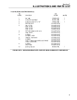
Page 48: ...Section 7 ILLUSTRATIONS AND PARTS LIST 42 7 10 CONTROL BOX...
Page 52: ...Section 7 ILLUSTRATIONS AND PARTS LIST 46 7 12 FRAME CANOPY AND PARTS...
Page 56: ...Section 7 ILLUSTRATIONS AND PARTS LIST 50 7 14 WYE DELTA ELECTRIC BOX ES 6...
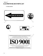
Page 58: ...Section 7 ILLUSTRATIONS AND PARTS LIST 52 7 15 DECAL GROUP 7 8 9 11 12...
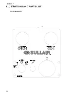
Page 60: ...Section 7 ILLUSTRATIONS AND PARTS LIST 54 7 15 DECAL GROUP 13...
Page 62: ...Section 7 ILLUSTRATIONS AND PARTS LIST 56 7 16 WIRING DIAGRAM SINGLE PHASE 60Hz...
Page 63: ...Section 7 ILLUSTRATIONS AND PARTS LIST 57 7 17 WIRING DIAGRAM THREE PHASE 60Hz...
Page 64: ...Section 7 ILLUSTRATIONS AND PARTS LIST 58 7 18 WIRING DIAGRAM 50 Hz...
Page 65: ...Section 7 ILLUSTRATIONS AND PARTS LIST 59 7 19 WIRING DIAGRAM 50 Hz WYE DELTA...
Page 66: ...NOTES...
Page 67: ...NOTES...


