background image

Section 1

SAFETY

1

1.1 GENERAL

Sullair Corporation and its subsidiaries design and

manufacture all of their products so they can be op-

erated safely. However, the responsibility for safe

operation rests with those who use and maintain

these products. The following safety precautions

are offered as a guide which, if conscientiously fol-

lowed, will minimize the possibility of accidents

throughout the useful life of this equipment.

The compressor should be operated only by those

who have been trained and delegated to do so, and

who have read and understood this Operator’s

Manual. Failure to follow the instructions, proce-

dures and safety precautions in this manual may re-

sult in accidents and injuries.

NEVER

start the compressor unless it is safe to do

so.

DO NOT

attempt to operate the compressor with

a known unsafe condition. Tag the compressor and

render it inoperative by disconnecting and locking

out all power at source or otherwise disabling its

prime mover so others who may not know of the un-

safe condition cannot attempt to operate it until the

condition is corrected.

Install, use and operate the compressor only in full

compliance with all pertinent OSHA regulations

and/or any applicable Federal, State, and Local

codes, standards and regulations.

DO NOT

modify the compressor and/or controls in

any way except with written factory approval.

While not specifically applicable to all types of com-

pressors with all types of prime movers, most of the

precautionary statements contained herein are ap-

plicable to most compressors and the concepts be-

hind these statements are generally applicable to all

compressors.

1.2 PERSONAL PROTECTIVE EQUIPMENT

Prior to installing or operating the compressor, own-

ers, employers and users should become familiar

with, and comply with, all applicable OSHA regula-

tions and/or any applicable Federal, State and Local

codes, standards, and regulations relative to per-

sonal protective equipment, such as eye and face

protective equipment, respiratory protective equip-

ment, equipment intended to protect the extremi-

ties, protective clothing, protective shields and barri-

ers and electrical protective equipment, as well as

noise exposure administrative and/or engineering

controls and/or personal hearing protective equip-

ment.

1.3 PRESSURE RELEASE

A.

Install an appropriate flow--limiting valve between

the service air outlet and the shut--off (throttle)

valve, either at the compressor or at any other point

along the air line, when an air hose exceeding 1/2”

(13mm) inside diameter is to be connected to the

shut--off (throttle) valve, to reduce pressure in case

of hose failure, per OSHA Standard 29 CFR

1926.302(b)(7) and/or any applicable Federal,

State and Local codes, standards and regulations.

B.

When the hose is to be used to supply a manifold,

install an additional appropriate flow--limiting valve

between the manifold and each air hose exceeding

1/2” (13mm) inside diameter that is to be connected

to the manifold to reduce pressure in case of hose

failure.

C.

Provide an appropriate flow--limiting valve at the

beginning of each additional 75 feet (23m) of hose in

runs of air hose exceeding 1/2” (13mm) inside diam-

eter to reduce pressure in case of hose failure.

D.

Flow--limiting valves are listed by pipe size and

rated CFM. Select appropriate valves accordingly,

in accordance with their manufacturer’s recommen-

dations.

E. DO NOT

use air tools that are rated below the

maximum rating of the compressor. Select air tools,

air hoses, pipes, valves, filters and other fittings ac-

cordingly.

DO NOT

exceed manufacturer’s rated

safe operating pressures for these items.

F.

Secure all hose connections by wire, chain or oth-

er suitable retaining device to prevent tools or hose

ends from being accidentally disconnected and ex-

pelled.

G.

Open fluid filler cap only when compressor

is not

running and is not pressurized.

Shut down the

compressor and bleed the sump (receiver) to zero

internal pressure before removing the cap.

H.

Vent all internal pressure prior to opening any

line, fitting, hose, valve, drain plug, connection or

other component, such as filters and line oilers, and

before attempting to refill optional air line anti--icer

systems with antifreeze compound.

I.

Keep personnel out of line with and away from the

discharge opening of hoses or tools or other points

of compressed air discharge.

J.

Use air at pressures less than 30 psig (2.1 bar) for

cleaning purposes, and then only with effective chip

guarding and personal protective equipment per

OSHA Standard 29 CFR 1910.242 (b) and/or any

applicable Federal, State, and Local codes, stan-

dards and regulations.

K. DO NOT

engage in horseplay with air hoses as

death or serious injury may result.

1.4 FIRE AND EXPLOSION

A.

Clean up spills of lubricant or other combustible

substances immediately, if such spills occur.

B.

Shut off the compressor and allow it to cool. Then

keep sparks, flames and other sources of ignition

away and

DO NOT

permit smoking in the vicinity

when checking or adding lubricant or when refilling

air line anti--icer systems with antifreeze compound.

C. DO NOT

permit fluids, including air line anti--icer

system antifreeze compound or fluid film, to accu-

Summary of Contents for ES-6 series

Page 1: ...ROTARY SCREW ES 6 Series 5 7 5 and 10HP OPERATOR S MANUAL AND Part Number 02250057 634 Sullair Corporation PARTS LIST AIR COMPRESSOR 4 5 5 and 7 5 kw KEEP FOR FUTURE REFERENCE...

Page 2: ...t Sullair s corporate headquarters in Michigan City Indiana Instruction includes discussion of the function and installation of Sullair service parts troubleshooting of the most common problems and ac...

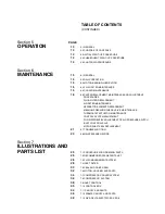
Page 3: ...NTS 5 2 3 ENCAPSULATED COMPRESSOR SYSTEM FUNCTIONAL DESCRIPTION 5 2 4 COMPRESSOR COOLING SYSTEM FUNCTIONAL DESCRIPTION 5 2 5 AIR INLET SYSTEM FUNCTIONAL DESCRIPTION 7 2 6 CONTROL SYSTEM FUNCTIONAL DES...

Page 4: ...REPLACEMENT MINIMUM PRESSURE CHECK VALVE MAINTENANCE THERMOSTAT ACTUATOR MAINTENANCE CONTROL SYSTEM ADJUSTMENT FOR DIFFERENTIAL ADJUSTMENT OF AIR PRESSURE SWITCH INLET CONTROL VALVE MOTOR SHAFT SEAL...

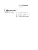
Page 5: ...ILLUSTRATIONS AND PARTS LIST CONT 50 7 14 WYE DELTA ELECTRIC BOX ES 6 52 7 15 DECAL GROUP 56 7 16 WIRING DIAGRAM SINGLE PHASE 60 Hz 57 7 17 WIRING DIAGRAM THREE PHASE 60 Hz 58 7 18 WIRING DIAGRAM 50...

Page 6: ...NOTES...

Page 7: ...an air hose exceeding 1 2 13mm inside diameter is to be connected to the shut off throttle valve to reduce pressure in case of hose failure per OSHA Standard 29 CFR 1926 302 b 7 and or any applicable...

Page 8: ...parts D Keep access doors if any closed except when making repairs or adjustments E Make sure all personnel are out of and or clear of the compressor prior to attempting to start or oper ate it F Disc...

Page 9: ...ressor is provided with a lifting bail then lift by the bail provided If no bail is provided then lift by sling Compressors to be air lifted by he licopter must not be supported by the lifting bail bu...

Page 10: ...enter it to perform service adjustments inform other per sonnel before doing so or else secure and tag the access door in the open position to avoid the possi bility of others closing and possibly lat...

Page 11: ...ng one rotor to directly drive the other which is an idler The air fluid mixture discharges directly into the fluid management system The fluid cooler bypass valve helps assure proper cooling by direc...

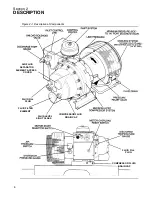
Page 12: ...Figure 2 1 Description of Components 4KW 5 5 7 5KW COMPRESSOR FLUID DRAIN CAP COMPRESSOR FLUID DRAIN CAP FLUID FILL PLUG FLUID FILL PLUG FLUID FILTER ELEMENT FLUID LEVEL SIGHT GLASS AIR FLUID SEPARAT...

Page 13: ...and the motor continues to run When the line pressure drops to the low setting of the pressure switch the pressure switch closes re energizing the normally open solenoid valve and al lowing the compr...

Page 14: ...is located on the left side of the electrical control center and a discharge temper ature gauge which is located on the right side of the electrical control center The line pressure gauge reads plant...

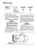
Page 15: ...495 325 150 ES 6 10XH 10 7 5 28 2 80 175 12 70 85 33 838 21 3 4 553 19 1 2 495 325 150 Model HP KW Capacity ACFM Maximum PSIG BAR Pressure Length in mm Width Height Weight lb kg 50Hz M3 MIN dBA I in m...

Page 16: ...lso be af fected I Plastic Pipe Institute Recommendation B Adopted January 19 1972 Maintenance of all other components is still recom mended as indicated in the Operator s Manual For light duty high h...

Page 17: ...d above ground locations e g in exposed plant piping I Sullube 32 should not be used with PVC piping systems It may affect the bond at cemented joints Certain other plastic materials may also be affec...

Page 18: ...stomer wiring is minimal but should be done by a qualified electrician in compliance with OSHA National Electrical Code and any other ap plicable State Federal and local electrical codes concerning is...

Page 19: ...erating temperature of 170qF 77qC Used for fast warm up and start up MINIMUM PRESSURE CHECK VALVE Maintains a minimum of 60 psig 4 1 bar in compres sor sump Valve piston restricts receiver air dischar...

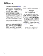
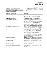
Page 20: ...is set correctly If set correctly the compressor will unload at nameplate pres sure If adjustments are necessary see Control System Adjustment in Section 6 Maintenance of this manual 8 Observe the op...

Page 21: ...an ring to the cooler 2 Remove the 1 8 NPT plugs in the filler and drain connection for both bearings 3 Free drain hole of any hard grease use piece of wire if necessary 4 Add grease I using a low pre...

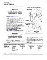
Page 22: ...so require WARNING Before doing compressor maintenance discon nect compressor from power source and lock out power source Isolate compressor from line pres sure by closing recommended discharge shut o...

Page 23: ...Figure 6 3 The separator should be changed once a year Follow the procedure ex plained below for element replacement WARNING Before doing compressor maintenance discon nect compressor from power sourc...

Page 24: ...all parts 4 Remove the screw holding the check valve seat Replace valve seat Reinstall securing with Loc titeR 222 5 Install new o ring Before reinstallation lubricate with Parker Super O ring seal or...

Page 25: ...OF AIR PRESSURE SWITCH Differential is the difference between the high and low pressure settings Turning the screw clockwise increases the differen tial and counterclockwise decreases the differential...

Page 26: ...crew washers and check spring from intake valve rod 7 Remove intake valve from valve housing Re move intake valve rod check spring spring re tainer and intake valve head 8 Remove intake piston from in...

Page 27: ...he Sullair Corporation factory TROUBLESHOOTING SYMPTOM PROBABLE CAUSE REMEDY COMPRESSOR WILL NOT START Main Disconnect Switch Open Close switch Line Fuse Blown Replace fuse Control Transformer Fuse Bl...

Page 28: ...s Fluid Foaming Drain and change Fluid Level Too High Drain excess Shaft Seal Failure Replace shaft seal PRESSURE RELIEF VALVE Compressor Operating Pressure See Symptom Line Pressure Rises Above OPENS...

Page 29: ...Section 6 MAINTENANCE 23 MODEL NO SERIAL NO 6 8 MAINTENANCE RECORD DATE HOURMETER MAINTENANCE PERFORMED WORK PERFORMED BY AUTHORIZED BY...

Page 30: ...Section 7 ILLUSTRATIONS AND PARTS LIST 24 ES 6 COMPRESSOR ASSEMBLY EXPLODED VIEW 5 5 AND 7 5KW...

Page 31: ...hone 33 72232425 Fax 33 78907168 Fax 219 874 1835 Parts Fax 219 874 1805 Service 1 219 879 5451 SULLAIR ASIA LTD Chiwan Supply Base Bldg A5 1 Chiwan Shenzhen Guangdong PRV P R C Post Code 518068 Telep...

Page 32: ...Section 7 ILLUSTRATIONS AND PARTS LIST 26 7 3 FLUID MANAGEMENT SYSTEM...

Page 33: ...actuator thermostat III 250025 413 1 12 piston thermostat 250025 415 1 13 spring compression 250025 464 1 14 pin roll 1 4 x 1 1 2 827404 150 1 15 guide thermostat spring 250025 417 1 16 o ring IV 2500...

Page 34: ...Section 7 ILLUSTRATIONS AND PARTS LIST 28 7 4 INLET FILTER...

Page 35: ...ing 1 4 20 824815 004 1 3 washer seal 250025 661 1 4 hood air filter 250025 422 1 5 element air filter I 250025 421 1 6 plate air filter base 250025 423 1 7 rod threaded 1 4 x 5 843504 050 1 I For mai...

Page 36: ...Section 7 ILLUSTRATIONS AND PARTS LIST 30 7 5 SEAL AND DRIVE GEAR...

Page 37: ...wear 250025 412 1 5 seal shaft Teflon Viton I 250039 218 1 6 capscrew ferry head 1 4 20 x 3 4 828404 075 2 7 housing shaft seal 250025 312 1 8 o ring 2 7 8 x 3 32 826502 150 1 9 spacer gear 250039 600...

Page 38: ...Section 7 ILLUSTRATIONS AND PARTS LIST 32 7 6 MOTOR HOUSING AND PARTS 7 5 10HP 5 5 7 5KW ONLY...

Page 39: ...elief 1 2 175 psig 12 1 bar 409955 1 Svalve relief 1 2 200 psig 13 8 bar 250039 678 1 12 plug pipe hex soc 1 8 NPT 490046 001 2 13 motor 5HP 4KW Consult Factory 1 Smotor 7 5HP 5 5KW Consult Factory 1...

Page 40: ...Section 7 ILLUSTRATIONS AND PARTS LIST 34 7 7 COMPRESSOR COOLER SYSTEM 7 5 10HP 5 5 7 5KW COOLER...

Page 41: ...5 5 and 7 5KW 828405 200 2 10 washer flat 5 16 id x 1 1 4 od 5HP 4KW 250025 830 1 Swasher flat 5 16 id x 1 1 4 od 7 5 10HP 5 5 and 7 5KW 250025 830 2 11 connector tube straight threaded 1 2 x 3 4 8118...

Page 42: ...Section 7 ILLUSTRATIONS AND PARTS LIST 36 7 8 COMPRESSOR SYSTEM...

Page 43: ...be 90M 1 4 x 1 4 250025 850 2 19 bearing cylinder roll plain 499082 705 1 20 bearing needle roller steel 250023 213 1 21 retainer inlet bearing 250025 435 1 22 screw machine flat head 1 4 20 x 1 2 831...

Page 44: ...Section 7 ILLUSTRATIONS AND PARTS LIST 38 7 9 INLET CONTROL...

Page 45: ...02250044 811 1 8 seal ES 6 intake control piston II 02250044 671 1 9 washer Belleville spring I 250031 269 2 10 capscrew sch 10 32 x 1 2 Nylok 02250043 162 1 11 spring inlet control ES 6 02250042 966...

Page 46: ...Section 7 ILLUSTRATIONS AND PARTS LIST 40 7 10 CONTROL BOX...

Page 47: ...al reset 02250045 011 1 18 screw 1 4 20 x 1 2 long 250030 162 4 19 fastener suregrip 041516 2 20 nameplate Sullair 1 x 6 250035 063 1 21 joint compression phase 230V 3PH 250026 615 1 Sphase 3 460V not...

Page 48: ...Section 7 ILLUSTRATIONS AND PARTS LIST 42 7 10 CONTROL BOX...

Page 49: ...828604 550 1 37 capacitor run 5HP 4KW single phase 250031 734 2 38 capacitor start 5HP 4KW single phase 250031 733 2 39 nut hex flanged 1 4 20 single phase 825304 236 1 40 support lower control box ES...

Page 50: ...Section 7 ILLUSTRATIONS AND PARTS LIST 44 7 11 CANOPY AND PARTS 1 2 3 4 5 6 7 8 9 10 11 12 13 14 15 16 17 18...

Page 51: ...et canopy ES 6 mounting right 250033 702 1 8 canopy stop ES 6 250033 096 2 9 decal Sullair logo not shown 02250059 052 1 10 decal ES 6 Model not shown 02250060 043 1 11 decal warning under pressure 02...

Page 52: ...Section 7 ILLUSTRATIONS AND PARTS LIST 46 7 12 FRAME CANOPY AND PARTS...

Page 53: ...2 hole 250034 583 1 36 screw hex serrated washer 1 4 x 1 2 829704 050 7 37 nut hex flange plated 1 4 20 825304 236 7 38 washer pl b regular plated 3 8 838206 071 8 39 bracket canopy adjustment 250025...

Page 54: ...Section 7 ILLUSTRATIONS AND PARTS LIST 48 7 13 WYE DELTA ELECTRIC BOX ES 6 LINE PRESSURE DISCHARGE TEMP MANUAL ON OFF RESET AUTO POWER ON 23 RE S ET 24...

Page 55: ...1 8 250025 849 3 14 tee male branch 1 8 250026 139 1 15 bushing reducing 3 8 x 1 8 807601 005 1 16 switch pressure range 40 150 250031 244 1 17 switch 3 position selector 250034 883 1 Sblock contact...

Page 56: ...Section 7 ILLUSTRATIONS AND PARTS LIST 50 7 14 WYE DELTA ELECTRIC BOX ES 6...

Page 57: ...ry Sfuse 4 amp Consult Factory Sfuse carrier Consult Factory 6 CPT with tamper proof cover Consult Factory 7 relay control Consult Factory 8 contactor Consult Factory Scontactor block Consult Factory...

Page 58: ...Section 7 ILLUSTRATIONS AND PARTS LIST 52 7 15 DECAL GROUP 7 8 9 11 12...

Page 59: ...direction 040745 1 8 decal compressor fluid Sullube 32 I 02250069 389 1 8B decal fluid SRF 1 4000 not shown I 02250069 391 1 9 decal earth ground 02250075 046 2 Sdecal protective earth ground not sho...

Page 60: ...Section 7 ILLUSTRATIONS AND PARTS LIST 54 7 15 DECAL GROUP 13...

Page 61: ...5 7 15 DECAL GROUP continued key part number description number quantity 13 decal ES 6 canopy bezel 02250061 884 1 14 decal mandatory read manual not shown 02250078 002 1 PLEASE NOTE WHEN ORDERING PAR...

Page 62: ...Section 7 ILLUSTRATIONS AND PARTS LIST 56 7 16 WIRING DIAGRAM SINGLE PHASE 60Hz...

Page 63: ...Section 7 ILLUSTRATIONS AND PARTS LIST 57 7 17 WIRING DIAGRAM THREE PHASE 60Hz...

Page 64: ...Section 7 ILLUSTRATIONS AND PARTS LIST 58 7 18 WIRING DIAGRAM 50 Hz...

Page 65: ...Section 7 ILLUSTRATIONS AND PARTS LIST 59 7 19 WIRING DIAGRAM 50 Hz WYE DELTA...

Page 66: ...NOTES...

Page 67: ...NOTES...

Page 68: ...33 72232425 Fax 33 78907168 SULLAIR CORPORATION Subsidiary of Sundstrand Corporation 3700 East Michigan Boulevard Michigan City Indiana 46360 U S A Telephone 1 800 SULLAIR U S A Only or 1 219 879 545...

Reviews: