Section 2
DESCRIPTION
7
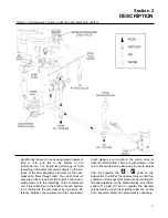
significantly reduced, thus causing large droplets of
fluid to form and fall to the bottom of the
receiver/sump. The fractional percentage of fluid
remaining in the compressed air collects on the sur-
faces of the dual separator elements as the com-
pressed air flows through them. Two return lines (or
scavenge tubes) lead from the bottom of each sep-
arator element to the interstage of the compressor
unit. Fluid collecting on the bottom of each separa-
tor is returned to the compressor by a pressure dif-
ference between the receiver and the compressor.
Sight glasses are located in the return lines to
observe this fluid flow. There are also orifices in this
return line (protected by strainers) to assure proper
flow. By pressing the
+
pads on the
Supervisor Controller, the operator may monitor the
condition of the separator elements by reading dif-
ferential pressure on the digital display. At a differ-
ential of 10 psid (0.7 bar) or greater, the operator
will be told to service the separator element. At this
time, separator element replacement is necessary.
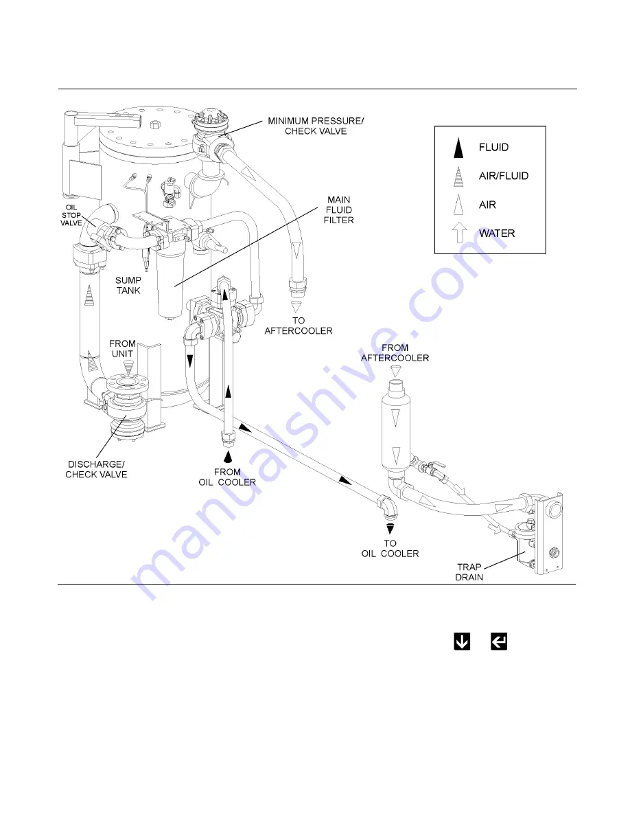
Figure 2-2 Compressor Cooling, Lubrication and Discharge System
Summary of Contents for LS-20T
Page 6: ......
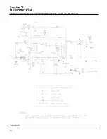
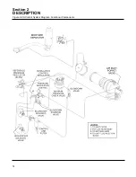
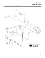
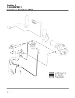
Page 20: ...Section 2 DESCRIPTION 14 Figure 2 4A Control System Diagram Functional Components...
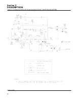
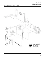
Page 21: ...Section 2 DESCRIPTION 15 Figure 2 4B Control System Diagram START...
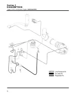
Page 22: ...Section 2 DESCRIPTION 16 Figure 2 4C Control System Diagram MODULATION...
Page 23: ...Section 2 DESCRIPTION 17 Figure 2 4D Control System Diagram FULL LOAD...
Page 24: ...Section 2 DESCRIPTION 18 Figure 2 4E Control System Diagram UNLOAD...
Page 26: ...NOTES 20...
Page 30: ...NOTES 24...
Page 34: ...NOTES 28...
Page 42: ...NOTES 36...
Page 46: ...NOTES 40...
Page 49: ...NOTES 43...
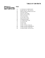
Page 50: ...Section 9 ILLUSTRATIONS AND PARTS LIST 44 02250137 909R00 9 3 MOTOR FRAME COMPRESSOR AND PARTS...
Page 52: ...Section 9 ILLUSTRATIONS AND PARTS LIST 46 02250137 907R03 9 4 AIR INLET SYSTEM...
Page 54: ...Section 9 ILLUSTRATIONS AND PARTS LIST 48 02250137 907R03 9 4 AIR INLET SYSTEM...
Page 56: ...Section 9 ILLUSTRATIONS AND PARTS LIST 50 02250138 702R00 9 5 AIR INLET SUB ASSEMBLY...
Page 58: ...Section 9 ILLUSTRATIONS AND PARTS LIST 52 02250137 908R00 9 6 WATER COOLING SYSTEM...
Page 60: ...Section 9 ILLUSTRATIONS AND PARTS LIST 54 02250137 910R01 9 7 AIR PIPING SYTEM...
Page 62: ...Section 9 ILLUSTRATIONS AND PARTS LIST 56 02250137 912R01 9 8 FLUID PIPING SYSTEM...
Page 64: ...Section 9 ILLUSTRATIONS AND PARTS LIST 58 02250139 798R00 9 9 WATER PIPING SYSTEM...
Page 66: ...Section 9 ILLUSTRATIONS AND PARTS LIST 60 02250137 911R01 9 10 DISCHARGE SYSTEM...
Page 68: ...Section 9 ILLUSTRATIONS AND PARTS LIST 62 02250137 911R01 9 10 DISCHARGE SYSTEM...
Page 70: ...Section 9 ILLUSTRATIONS AND PARTS LIST 64 02250137 911R01 9 10 DISCHARGE SYSTEM...
Page 72: ...Section 9 ILLUSTRATIONS AND PARTS LIST 66 02250137 914R02 9 11 CONTROL START SYSTEM...
Page 74: ...Section 9 ILLUSTRATIONS AND PARTS LIST 68 02250137 914R02 9 11 CONTROL START SYSTEM...
Page 76: ...Section 9 ILLUSTRATIONS AND PARTS LIST 70 9 12 CONTROL PANEL 02250138 633R00...
Page 78: ...Section 9 ILLUSTRATIONS AND PARTS LIST 72 9 13 ENCLOSURE 02250138 672R00...
Page 80: ...Section 9 ILLUSTRATIONS AND PARTS LIST 74 9 13 ENCLOSURE 02250138 672R00...
Page 82: ...Section 9 ILLUSTRATIONS AND PARTS LIST 76 9 14 DECAL GROUP...
Page 84: ...Section 9 ILLUSTRATIONS AND PARTS LIST 78 9 14 DECAL GROUP...
Page 86: ...Section 9 ILLUSTRATIONS AND PARTS LIST 80 9 14 DECAL GROUP...
Page 88: ...Section 9 ILLUSTRATIONS AND PARTS LIST 82 9 15 DECAL LOCATION OPEN MODEL...
Page 90: ...Section 9 ILLUSTRATIONS AND PARTS LIST 84 9 16 DECAL LOCATION ENCLOSED MODEL...
Page 92: ...Section 9 ILLUSTRATIONS AND PARTS LIST 86 9 17 DECAL LOCATION CONTROL BOX...
Page 94: ...Section 9 ILLUSTRATIONS AND PARTS LIST 88 9 18 WIRING DIAGRAM LS20T 525 PSIG 02250137 917R01...
Page 95: ...NOTES 89...


