Section 2
DESCRIPTION
14
the Sullicon Control, which starts partially closing
the inlet butterfly valve. The inlet butterfly valve pro-
vides modulation range from 50 to 40%. During this
period, the pressure rises approximately from 66 to
70 psig (4.1 to 4.8 bar). During this range, the spi-
ral valve remains in the full open position.
UNLOAD MODE - IN EXCESS OF 70 PSIG (4.8
BAR)
When a relatively small amount or no air is being
used, the service line pressure continues to rise.
When it exceeds 70 psig (4.8 bar), Supervisor
Controller de-energizes the solenoid valve allowing
line pressure to be supplied directly to the Sullicon
diaphragm keeping the inlet butterfly closed; the
spiral valve is in the fully open (minimum) position.
Simultaneously, the solenoid valve sends a pneu-
matic signal to the blowdown valve. The blowdown
valve opens the sump to the atmosphere. This
reduces the sump pressure to approximately 30
psig (2.1 bar) which results in low horsepower con-
sumption. The check valve in the air service line
prevents line pressure from returning to sump while
the compressor is running in the unloaded mode.
Both the spiral valve and the butterfly valve remain
in the unload position.
When the line pressure drops back to 60 psig (4.2
bar) due to an increase in the air demand,
Supervisor Controller energizes the solenoid valve
allowing the air pressure behind the Sullicon
Control to be vented through the solenoid valve
exhaust port. The blowdown valve closes, and the
inlet butterfly valve opens. Also the air pressure at
the spiral valve actuator diaphragm is reduced
through a vent hole at the spiral valve differential
pressure regulator, and a spring in the actuator
causes the spiral valve to return to the full load
(maximum) position.
AUTOMATIC OPERATION
For applications with varied periods of time when
there are no air requirements, Supervisor’s Auto
mode allows the compressor to shut down (time
delayed) when no compressed air requirement is
present and restart as compressed air is needed.
LOAD/ NO LOAD OPERATION
If applications call for load/no load operation, mod-
ulation can be disabled in the Supervisor
Controller
TM
in the “Control Parameters” menu. If
modulation is disabled, the unload pressure must
be reset to the rated load pressure of the machine.
For example, an LL model rated for 60 psig full load
operation and 70 psig unload must have the unload
pressure reset to 60 psig. This ensures that the
motor will not run in an overload condition.
Summary of Contents for LS-32
Page 6: ...NOTES...
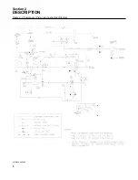
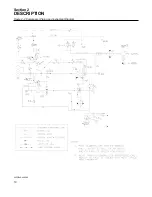
Page 14: ...Section 2 DESCRIPTION 8 Figure 2 2 Compressor Piping and Instrument Diagram 02250140 998R02...
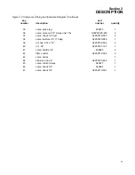
Page 16: ...Section 2 DESCRIPTION 10 Figure 2 2 Compressor Piping and Instrument Diagram 02250140 998R02...
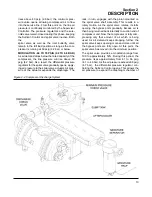
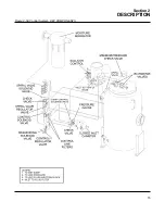
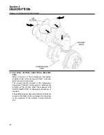
Page 21: ...Section 2 DESCRIPTION 15 Figure 2 5A Control System KEY COMPONENTS...
Page 22: ...Section 2 DESCRIPTION 16 Figure 2 5B Control System START...
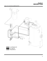
Page 23: ...Section 2 DESCRIPTION 17 Figure 2 5C Control System MODULATION...
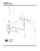
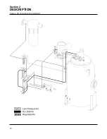
Page 24: ...Section 2 DESCRIPTION 18 Figure 2 5D Control System UNLOAD...
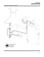
Page 25: ...Section 2 DESCRIPTION 19 Figure 2 5E Control System FULL LOAD...
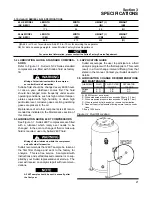
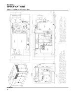
Page 28: ...Section 3 SPECIFICATIONS 22 Figure 3 2 Identification LS 32 Air cooled 02250140 997R01...
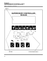
Page 32: ...Section 5 SUPERVISOR CONTROLLER 26 Figure 5 1 Supervisor Control Panel...
Page 44: ...38 NOTES...
Page 56: ...50 NOTES...
Page 59: ...53 NOTES...
Page 60: ...Section 8 ILLUSTRATIONS AND PARTS LIST 54 8 3 MOTOR COMPRESSOR FRAME AND PARTS 02250140 989R01...
Page 62: ...Section 8 ILLUSTRATIONS AND PARTS LIST 56 8 3 MOTOR COMPRESSOR FRAME AND PARTS 02250140 989R01...
Page 64: ...Section 8 ILLUSTRATIONS AND PARTS LIST 58 8 4 AIR INLET SYSTEM 02250140 990R02...
Page 66: ...Section 8 ILLUSTRATIONS AND PARTS LIST 60 8 4 AIR INLET SYSTEM 02250140 990R02...
Page 68: ...Section 8 ILLUSTRATIONS AND PARTS LIST 62 8 5 FLUID COOLING SYSTEM AIR COOLED 02250140 994R00...
Page 70: ...Section 8 ILLUSTRATIONS AND PARTS LIST 64 8 5 FLUID COOLING SYSTEM AIR COOLED 02250140 994R00...
Page 72: ...Section 8 ILLUSTRATIONS AND PARTS LIST 66 8 6 AIR PIPING SYSTEM AIR COOLED 02250140 992R01...
Page 74: ...Section 8 ILLUSTRATIONS AND PARTS LIST 68 8 6 AIR PIPING SYSTEM AIR COOLED 02250140 992R01...
Page 76: ...Section 8 ILLUSTRATIONS AND PARTS LIST 70 02250140 993R01 8 7 FLUID PIPING SYSTEM AIR COOLER...
Page 78: ...Section 8 ILLUSTRATIONS AND PARTS LIST 72 02250140 993R01 8 7 FLUID PIPING SYSTEM AIR COOLER...
Page 80: ...Section 8 ILLUSTRATIONS AND PARTS LIST 74 02250140 991R00 8 8 SUMP AND PARTS...
Page 82: ...Section 8 ILLUSTRATIONS AND PARTS LIST 76 02250140 991R00 8 8 SUMP AND PARTS...
Page 84: ...Section 8 ILLUSTRATIONS AND PARTS LIST 78 8 9 SULLICON CONTROL 02250134 158R00...
Page 86: ...Section 8 ILLUSTRATIONS AND PARTS LIST 80 8 10 COMPRESSOR ACTUATOR...
Page 88: ...Section 8 ILLUSTRATIONS AND PARTS LIST 82 8 11 PNEUMATIC CONTROLS 02250140 996R00...
Page 90: ...Section 8 ILLUSTRATIONS AND PARTS LIST 84 8 11 PNEUMATIC CONTROLS 02250140 996R00...
Page 92: ...Section 8 ILLUSTRATIONS AND PARTS LIST 86 8 11 PNEUMATIC CONTROLS 02250140 996R00...
Page 94: ...Section 8 ILLUSTRATIONS AND PARTS LIST 88 8 12 CONTROL BOX SOLID STATE 02250122 005R04...
Page 96: ...Section 8 ILLUSTRATIONS AND PARTS LIST 90 8 13 CONTROL BOX FULL VOLTAGE 02250122 511R04...
Page 98: ...Section 8 ILLUSTRATIONS AND PARTS LIST 92 8 14 CONTROL BOX WYE DELTA 02250122 516R08...
Page 100: ...Section 8 ILLUSTRATIONS AND PARTS LIST 94 8 15 ENCLOSURE AIR COOLED 02250140 995R00...
Page 102: ...Section 8 ILLUSTRATIONS AND PARTS LIST 96 8 15 ENCLOSURE AIR COOLED 02250140 995R00...
Page 104: ...Section 8 ILLUSTRATIONS AND PARTS LIST 98 8 16 DECAL GROUP...
Page 106: ...Section 8 ILLUSTRATIONS AND PARTS LIST 100 8 16 DECAL GROUP...
Page 108: ...Section 8 ILLUSTRATIONS AND PARTS LIST 102 8 16 DECAL GROUP...
Page 110: ...Section 8 ILLUSTRATIONS AND PARTS LIST 104 8 17 DECAL LOCATIONS...
Page 112: ...Section 8 ILLUSTRATIONS AND PARTS LIST 106 8 18 DECAL LOCATIONS ENCLOSURE...
Page 114: ...Section 8 ILLUSTRATIONS AND PARTS LIST 108 8 19 DECAL LOCATIONS CONTROL BOX...
Page 117: ...111 NOTES...

