Section 5
SUPERVISOR CONTROLLER™
34
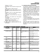
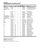
Table 5-1 Alarms
Start
Run
Sensor
Type Limit
Delay
Delay Check
(*)
Comment
System Check
On Fault
0
0
0
Constantly
Factory Setup Check Sum Fail
I/O Module Check
On Fault
0
0
0
Constantly
Communication failure I/O Module
Com Module Check
On Fault
0
0
0
Constantly
Communication failure Com Module
Motor Module Check
On Fault
0
0
0
Constantly
Communication failure Motor
Module
D_1
On Fault
0
1
1
Constantly
Motor overload
D_2
On Fault
0
1
1
Constantly
Aux motor overload
D_3
On Warn
0
5
5
When Running
Air filter maintenance
D_4
On Fault
0
5
5
When Running
Low water pressure
E_1
On Fault
0
0
0
Constantly
E-Stop Push Button
E_2
On Fault
0
0
0
Constantly
Auxiliary E-Stop
AIR FILTER MAINT.
Maint Warn
0
0
0
If Enabled
Air Filter change due
OIL ANALYSIS Check
Maint Warn
0
0
0
If Enabled
Oil Analysis due
OIL CHANGE Check
Maint Warn
0
0
0
If Enabled
Oil change due
OIL FILTER MAINT.
Maint Warn
0
0
0
If Enabled
Oil filter change due
SEPARATOR CHANGE
Check
Maint Warn
0
0
0
If Enabled
Separator change due
dP_1
High Warn
10
5
55
Over Min Psi
Separator maint P1-P2
dP_2
High Warn
20
5
2
When Running
Oil filter maint P4-P3
dP_3
Low Fault
1
5
55
When Running
Low Oil psi P3-(P1/2.5)
dP1Max
High Fault
0
5
0
When Running
dP1Max = P1Max - P1
dP1Max
High Warn
3
5
0
When Running
dP1Max = P1Max - P1
P_1
High Inhibit
5
0
0
At Start
High sump psi at start
P_1
Low Fault
5
5
0
When Running
Immediate Fault
P_1
High Fault
500
0
0
Constantly
Sensor failure fault
P_2
High Fault
500
0
0
Constantly
Sensor failure fault
P_3
High Fault
500
0
0
Constantly
Sensor failure fault
P_4
High Fault
500
0
0
Constantly
Sensor failure fault
T_1
Low Fault
-40
0
0
Constantly
Sensor failure fault
T_1
High Warn
225
5
30
Constantly
Delayed for temp spikes
T_1
High Fault
235
5
30
Constantly
Delayed for temp spikes
T_1
High Warn
245
0
0
Constantly
Immediate Warning
T_1
High Fault
255
0
0
Constantly
Immediate Fault
T_1
High Fault
500
0
0
Constantly
Sensor failure fault
T_2
Low Fault
-40
0
0
Constantly
Sensor failure fault
T_2
High Warn
225
5
30
Constantly
Delayed for temp spikes
T_2
High Fault
235
5
30
Constantly
Delayed for temp spikes
T_3
Low Warn
-40
0
0
Constantly
Sensor failure warning
T_3
High Warn
500
0
0
Constantly
Sensor failure warning
T_4
Low Fault
-40
0
0
Constantly
Sensor failure fault
T_4
High Fault
500
0
0
Constantly
Sensor failure fault
(*)
In the ‘Check’ column above, alarms are checked
:
Constantly -
if machine running or stopped
When Running
- if machine is running
If Enabled -
if parameter is non-zero
At Start -
will not allow start if alarm present
Over Min Psi -
machine is loaded and above min load pressure
Summary of Contents for LS-32
Page 6: ...NOTES...
Page 14: ...Section 2 DESCRIPTION 8 Figure 2 2 Compressor Piping and Instrument Diagram 02250140 998R02...
Page 16: ...Section 2 DESCRIPTION 10 Figure 2 2 Compressor Piping and Instrument Diagram 02250140 998R02...
Page 21: ...Section 2 DESCRIPTION 15 Figure 2 5A Control System KEY COMPONENTS...
Page 22: ...Section 2 DESCRIPTION 16 Figure 2 5B Control System START...
Page 23: ...Section 2 DESCRIPTION 17 Figure 2 5C Control System MODULATION...
Page 24: ...Section 2 DESCRIPTION 18 Figure 2 5D Control System UNLOAD...
Page 25: ...Section 2 DESCRIPTION 19 Figure 2 5E Control System FULL LOAD...
Page 28: ...Section 3 SPECIFICATIONS 22 Figure 3 2 Identification LS 32 Air cooled 02250140 997R01...
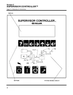
Page 32: ...Section 5 SUPERVISOR CONTROLLER 26 Figure 5 1 Supervisor Control Panel...
Page 44: ...38 NOTES...
Page 56: ...50 NOTES...
Page 59: ...53 NOTES...
Page 60: ...Section 8 ILLUSTRATIONS AND PARTS LIST 54 8 3 MOTOR COMPRESSOR FRAME AND PARTS 02250140 989R01...
Page 62: ...Section 8 ILLUSTRATIONS AND PARTS LIST 56 8 3 MOTOR COMPRESSOR FRAME AND PARTS 02250140 989R01...
Page 64: ...Section 8 ILLUSTRATIONS AND PARTS LIST 58 8 4 AIR INLET SYSTEM 02250140 990R02...
Page 66: ...Section 8 ILLUSTRATIONS AND PARTS LIST 60 8 4 AIR INLET SYSTEM 02250140 990R02...
Page 68: ...Section 8 ILLUSTRATIONS AND PARTS LIST 62 8 5 FLUID COOLING SYSTEM AIR COOLED 02250140 994R00...
Page 70: ...Section 8 ILLUSTRATIONS AND PARTS LIST 64 8 5 FLUID COOLING SYSTEM AIR COOLED 02250140 994R00...
Page 72: ...Section 8 ILLUSTRATIONS AND PARTS LIST 66 8 6 AIR PIPING SYSTEM AIR COOLED 02250140 992R01...
Page 74: ...Section 8 ILLUSTRATIONS AND PARTS LIST 68 8 6 AIR PIPING SYSTEM AIR COOLED 02250140 992R01...
Page 76: ...Section 8 ILLUSTRATIONS AND PARTS LIST 70 02250140 993R01 8 7 FLUID PIPING SYSTEM AIR COOLER...
Page 78: ...Section 8 ILLUSTRATIONS AND PARTS LIST 72 02250140 993R01 8 7 FLUID PIPING SYSTEM AIR COOLER...
Page 80: ...Section 8 ILLUSTRATIONS AND PARTS LIST 74 02250140 991R00 8 8 SUMP AND PARTS...
Page 82: ...Section 8 ILLUSTRATIONS AND PARTS LIST 76 02250140 991R00 8 8 SUMP AND PARTS...
Page 84: ...Section 8 ILLUSTRATIONS AND PARTS LIST 78 8 9 SULLICON CONTROL 02250134 158R00...
Page 86: ...Section 8 ILLUSTRATIONS AND PARTS LIST 80 8 10 COMPRESSOR ACTUATOR...
Page 88: ...Section 8 ILLUSTRATIONS AND PARTS LIST 82 8 11 PNEUMATIC CONTROLS 02250140 996R00...
Page 90: ...Section 8 ILLUSTRATIONS AND PARTS LIST 84 8 11 PNEUMATIC CONTROLS 02250140 996R00...
Page 92: ...Section 8 ILLUSTRATIONS AND PARTS LIST 86 8 11 PNEUMATIC CONTROLS 02250140 996R00...
Page 94: ...Section 8 ILLUSTRATIONS AND PARTS LIST 88 8 12 CONTROL BOX SOLID STATE 02250122 005R04...
Page 96: ...Section 8 ILLUSTRATIONS AND PARTS LIST 90 8 13 CONTROL BOX FULL VOLTAGE 02250122 511R04...
Page 98: ...Section 8 ILLUSTRATIONS AND PARTS LIST 92 8 14 CONTROL BOX WYE DELTA 02250122 516R08...
Page 100: ...Section 8 ILLUSTRATIONS AND PARTS LIST 94 8 15 ENCLOSURE AIR COOLED 02250140 995R00...
Page 102: ...Section 8 ILLUSTRATIONS AND PARTS LIST 96 8 15 ENCLOSURE AIR COOLED 02250140 995R00...
Page 104: ...Section 8 ILLUSTRATIONS AND PARTS LIST 98 8 16 DECAL GROUP...
Page 106: ...Section 8 ILLUSTRATIONS AND PARTS LIST 100 8 16 DECAL GROUP...
Page 108: ...Section 8 ILLUSTRATIONS AND PARTS LIST 102 8 16 DECAL GROUP...
Page 110: ...Section 8 ILLUSTRATIONS AND PARTS LIST 104 8 17 DECAL LOCATIONS...
Page 112: ...Section 8 ILLUSTRATIONS AND PARTS LIST 106 8 18 DECAL LOCATIONS ENCLOSURE...
Page 114: ...Section 8 ILLUSTRATIONS AND PARTS LIST 108 8 19 DECAL LOCATIONS CONTROL BOX...
Page 117: ...111 NOTES...

