Section 6
COMPRESSOR OPERATION
35
6.1 INTRODUCTION
While Sullair has built into the LS-32 Series pack-
age a comprehensive array of controls and indica-
tors to assure its proper operation, the user should
recognize and interpret readings which call for
service or indicate the onset of a malfunction.
Before starting the unit, the user should become
familiar with the controls and indicators-their pur-
pose, location, and use.
6.2 PURPOSE OF CONTROLS
All Supervisor Controller related functions and indi-
cators are presented in Section 5.2, so please refer
to that section for your information. Additional indi-
cators and functions included in the package are as
follows:
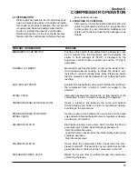
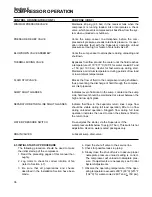
EMERGENCY STOP SWITCH
THERMAL O/L RESET
SULLICON ACTUATOR
SPIRAL VALVE
PRESSURE REGULATOR (SULLICON)
PRESSURE REGULATOR (WITH
SPIRAL VALVE)
SOLENOID VALVE #1
SOLENOID VALVE #2
DISCHARGE CHECK VALVE
Pushing in this switch, found adjacent to the Supervisor, cuts
all AC outputs from the Supervisor and de-energizes the
starter. A fault message (E STOP) is displayed by the
Supervisor until the button is pulled out and the “O” pad is
depressed.
Momentarily pushing this button, found on the starter’s ther-
mal overload element housing, re-closes the starter’s con-
tacts after a current overload takes place. Please be aware
that the elements must be allowed to cool sufficiently before
resetting.
Actuates the inlet butterfly valve which throttles the air flow to
the compressor inlet, in order to match air supply to the
demand.
Internally bypasses and controls the air flow capacity of the
compressor, in order to match air supply to the demand.
Opens a pressure line between the sump and Sullicon
Control allowing the Sullicon Control to regulate air delivery
according to the air demand.
Opens a pressure line between the service line and the spiral
valve actuator allowing the spiral valve to regulate air delivery
according to air demand.
Electrically actuated, 3-way valve which controls the flow of
pneumatic logic signals. Used throughout package to:
·
Open the blowdown valve.
·
Load the Sullicon device/close the inlet butterfly valve during
shutdown operation.
·
Open the spiral valve.
Opens when the compressor starts; closes when the com-
pressor is shut off. This prevents any air system loss and de-
pressurizes the controls when the compressor is shut off.
Blocks the reverse flow of air/fluid through the compressor
unit during shutdown.
CONTROL OR INDICATOR
PURPOSE
Summary of Contents for LS-32
Page 6: ...NOTES...
Page 14: ...Section 2 DESCRIPTION 8 Figure 2 2 Compressor Piping and Instrument Diagram 02250140 998R02...
Page 16: ...Section 2 DESCRIPTION 10 Figure 2 2 Compressor Piping and Instrument Diagram 02250140 998R02...
Page 21: ...Section 2 DESCRIPTION 15 Figure 2 5A Control System KEY COMPONENTS...
Page 22: ...Section 2 DESCRIPTION 16 Figure 2 5B Control System START...
Page 23: ...Section 2 DESCRIPTION 17 Figure 2 5C Control System MODULATION...
Page 24: ...Section 2 DESCRIPTION 18 Figure 2 5D Control System UNLOAD...
Page 25: ...Section 2 DESCRIPTION 19 Figure 2 5E Control System FULL LOAD...
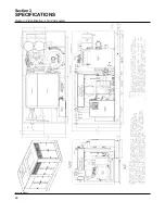
Page 28: ...Section 3 SPECIFICATIONS 22 Figure 3 2 Identification LS 32 Air cooled 02250140 997R01...
Page 32: ...Section 5 SUPERVISOR CONTROLLER 26 Figure 5 1 Supervisor Control Panel...
Page 44: ...38 NOTES...
Page 56: ...50 NOTES...
Page 59: ...53 NOTES...
Page 60: ...Section 8 ILLUSTRATIONS AND PARTS LIST 54 8 3 MOTOR COMPRESSOR FRAME AND PARTS 02250140 989R01...
Page 62: ...Section 8 ILLUSTRATIONS AND PARTS LIST 56 8 3 MOTOR COMPRESSOR FRAME AND PARTS 02250140 989R01...
Page 64: ...Section 8 ILLUSTRATIONS AND PARTS LIST 58 8 4 AIR INLET SYSTEM 02250140 990R02...
Page 66: ...Section 8 ILLUSTRATIONS AND PARTS LIST 60 8 4 AIR INLET SYSTEM 02250140 990R02...
Page 68: ...Section 8 ILLUSTRATIONS AND PARTS LIST 62 8 5 FLUID COOLING SYSTEM AIR COOLED 02250140 994R00...
Page 70: ...Section 8 ILLUSTRATIONS AND PARTS LIST 64 8 5 FLUID COOLING SYSTEM AIR COOLED 02250140 994R00...
Page 72: ...Section 8 ILLUSTRATIONS AND PARTS LIST 66 8 6 AIR PIPING SYSTEM AIR COOLED 02250140 992R01...
Page 74: ...Section 8 ILLUSTRATIONS AND PARTS LIST 68 8 6 AIR PIPING SYSTEM AIR COOLED 02250140 992R01...
Page 76: ...Section 8 ILLUSTRATIONS AND PARTS LIST 70 02250140 993R01 8 7 FLUID PIPING SYSTEM AIR COOLER...
Page 78: ...Section 8 ILLUSTRATIONS AND PARTS LIST 72 02250140 993R01 8 7 FLUID PIPING SYSTEM AIR COOLER...
Page 80: ...Section 8 ILLUSTRATIONS AND PARTS LIST 74 02250140 991R00 8 8 SUMP AND PARTS...
Page 82: ...Section 8 ILLUSTRATIONS AND PARTS LIST 76 02250140 991R00 8 8 SUMP AND PARTS...
Page 84: ...Section 8 ILLUSTRATIONS AND PARTS LIST 78 8 9 SULLICON CONTROL 02250134 158R00...
Page 86: ...Section 8 ILLUSTRATIONS AND PARTS LIST 80 8 10 COMPRESSOR ACTUATOR...
Page 88: ...Section 8 ILLUSTRATIONS AND PARTS LIST 82 8 11 PNEUMATIC CONTROLS 02250140 996R00...
Page 90: ...Section 8 ILLUSTRATIONS AND PARTS LIST 84 8 11 PNEUMATIC CONTROLS 02250140 996R00...
Page 92: ...Section 8 ILLUSTRATIONS AND PARTS LIST 86 8 11 PNEUMATIC CONTROLS 02250140 996R00...
Page 94: ...Section 8 ILLUSTRATIONS AND PARTS LIST 88 8 12 CONTROL BOX SOLID STATE 02250122 005R04...
Page 96: ...Section 8 ILLUSTRATIONS AND PARTS LIST 90 8 13 CONTROL BOX FULL VOLTAGE 02250122 511R04...
Page 98: ...Section 8 ILLUSTRATIONS AND PARTS LIST 92 8 14 CONTROL BOX WYE DELTA 02250122 516R08...
Page 100: ...Section 8 ILLUSTRATIONS AND PARTS LIST 94 8 15 ENCLOSURE AIR COOLED 02250140 995R00...
Page 102: ...Section 8 ILLUSTRATIONS AND PARTS LIST 96 8 15 ENCLOSURE AIR COOLED 02250140 995R00...
Page 104: ...Section 8 ILLUSTRATIONS AND PARTS LIST 98 8 16 DECAL GROUP...
Page 106: ...Section 8 ILLUSTRATIONS AND PARTS LIST 100 8 16 DECAL GROUP...
Page 108: ...Section 8 ILLUSTRATIONS AND PARTS LIST 102 8 16 DECAL GROUP...
Page 110: ...Section 8 ILLUSTRATIONS AND PARTS LIST 104 8 17 DECAL LOCATIONS...
Page 112: ...Section 8 ILLUSTRATIONS AND PARTS LIST 106 8 18 DECAL LOCATIONS ENCLOSURE...
Page 114: ...Section 8 ILLUSTRATIONS AND PARTS LIST 108 8 19 DECAL LOCATIONS CONTROL BOX...
Page 117: ...111 NOTES...

