Section 7
MAINTENANCE
31
AIR FILTER ELEMENT REMOVAL
1. Clean exterior of air filter housing.
2. Remove the cover/element assembly by loosen-
ing the wing nut securing it.
3. Pull the cover/element assembly out of the hous-
ing.
4. On the inside of the element, you will notice a
lock ring, which fastens the cover to the ele-
ment. Remove the lock ring and pull the cover
and element apart.
5. Clean the interior of the housing by using a damp
cloth.
DO NOT
blow dirt with compressed air.
6. Inspect the secondary element and replace if
necessary. This element is
NOT
cleanable.
7. To remove the secondary element, unscrew the
secondary restriction indicator from the threaded
rod running through the element. Pull the ele-
ment out of the housing.
8. Install the new secondary element and replace
the restriction indicator.
9. With the secondary element in place, clean or
replace the primary element. Cleaning instruc-
tions follow.
ELEMENT INSPECTION
1. Place a bright light inside the element to inspect
for damage or leak holes. Concentrated light
will shine through the element and disclose any
holes.
2. Inspect all gaskets and gasket contact surfaces
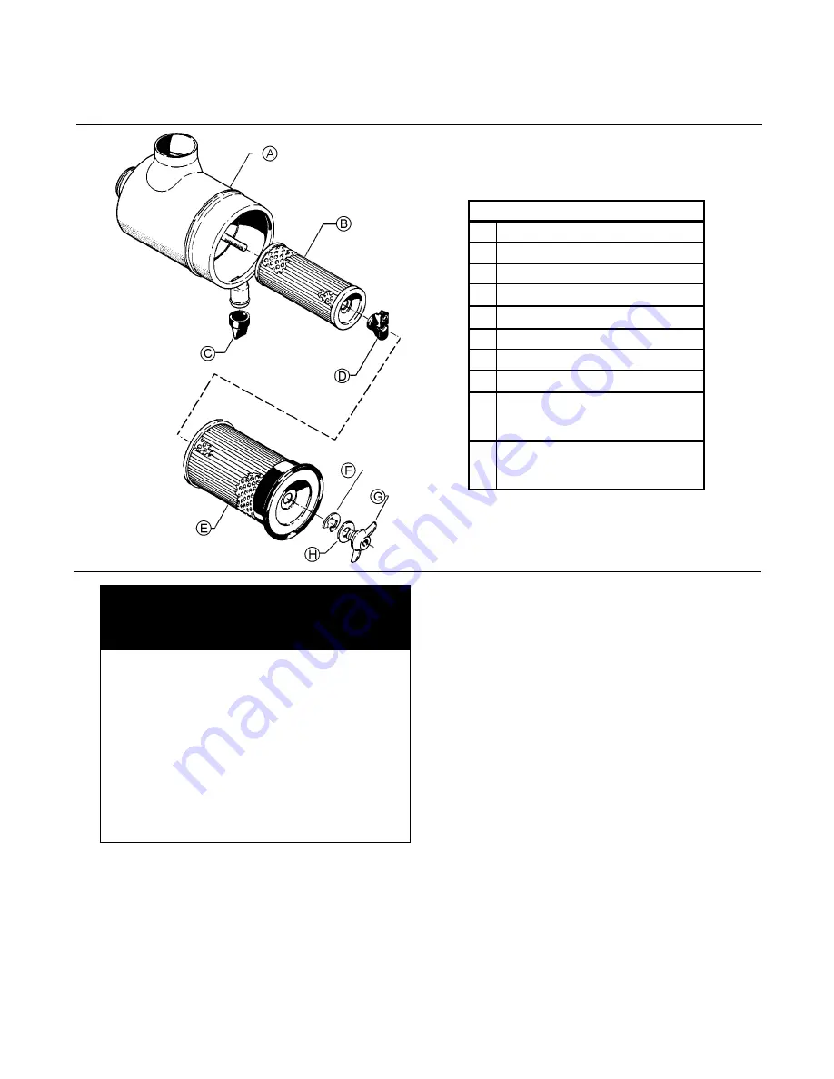
Figure 7-2 Air Filter Replacement (P/N 048456)
What you may need to perform
this maintenance (continued):
Secondary replacement element no.
048463
Cleaning materials (dampened cloth,
etc.) for cleaning exterior of housing
Damp cloth (separate from that used on
exterior) for cleaning interior of housing
Clean container (if new element is to be
stored for later use)
(Optional) Light source to check for
damage and/or leaks in filter element
KEY
A
HOUSING
B
SECONDARY ELEMENT**
C
DUST COVER
D
SAFETY SIGNAL
E
PRIMARY ELEMENT*
F
RETAINING CLIP
G
WING NUT
H
SEALING WASHER
*
REPLACEMENT ELEMENT
P/N: 02250135-150 (Primary)
**
REPLACEMENT ELEMENT
P/N: 048463 (Secondary)
Summary of Contents for LS20T 1100 CFM
Page 18: ...Section 2 DESCRIPTION 12 Figure 2 3B Control System Diagram START...
Page 19: ...Section 2 DESCRIPTION 13 Figure 2 3C Control System Diagram MODULATION...
Page 20: ...Section 2 DESCRIPTION 14 Figure 2 3D Control System Diagram FULL LOAD...
Page 21: ...Section 2 DESCRIPTION 15 Figure 2 3E Control System Diagram UNLOAD...
Page 44: ...NOTES 38...
Page 104: ...Section 9 ILLUSTRATIONS AND PARTS LIST 98 02250146 367R00 9 19 CONTROL START SYSTEM...
Page 106: ...Section 9 ILLUSTRATIONS AND PARTS LIST 100 02250146 367R00 9 19 CONTROL START SYSTEM...
Page 108: ...Section 9 ILLUSTRATIONS AND PARTS LIST 102 02250138 633R00 9 20 CONTROL PANEL...
Page 110: ...Section 9 ILLUSTRATIONS AND PARTS LIST 104 02250139 119R01 9 21 ENCLOSURE...
Page 112: ...Section 9 ILLUSTRATIONS AND PARTS LIST 106 02250139 119R01 9 21 ENCLOSURE...
Page 114: ...Section 9 ILLUSTRATIONS AND PARTS LIST 108 9 22 DECAL GROUP...
Page 116: ...Section 9 ILLUSTRATIONS AND PARTS LIST 110 9 22 DECAL GROUP...
Page 118: ...Section 9 ILLUSTRATIONS AND PARTS LIST 112 9 22 DECAL GROUP...
Page 120: ...Section 9 ILLUSTRATIONS AND PARTS LIST 114 9 23 DECAL LOCATIONS OPEN AIR COOLED...
Page 122: ...Section 9 ILLUSTRATIONS AND PARTS LIST 116 9 24 DECAL LOCATIONS OPEN WATER COOLED...
Page 124: ...Section 9 ILLUSTRATIONS AND PARTS LIST 118 9 25 DECAL LOCATIONS REMOTE COOLER...
Page 126: ...Section 9 ILLUSTRATIONS AND PARTS LIST 120 9 26 DECAL LOCATIONS CONTROL BOX...
Page 128: ...Section 9 ILLUSTRATIONS AND PARTS LIST 122 9 27 ENCLOSURE DECALS...
Page 145: ...NOTES 139...


