Section 2
11
OIL WATER SEPARATOR
INSTALLATION & MAINTENANCE
2.1
PLACE OF INSTALLATION
The OWS shall be installed on a clean, smooth and
level surface. The OWS must be installed
horizontally and should not be installed in direct
sunlight.
2.2
FLOW OF CONDENSATE
The condensate can be fed with or without pressure.
2.3
CONNECTIONS
See
.
2.4
START-UP
OWS - 88
Remove lid and filter. Fill the OWS with water until
the water runs out of the water discharge. Insert the
filter. Clean the tank and water inlet as needed. Re-
install the lid and filter, the device is now ready for
operation.
OWS - 2I0/420
Unscrew the dome. Fill the OWS with water until
water runs out of water discharge. Insert the filter.
Clean the tank and the water inlet as needed. Secure
the dome back on, the OWS is now ready for
operation.
OWS - 880-2I00
Unscrew the lid. Fill the OWS with water until water
runs out of water discharge. Insert the filter. Clean
the tank and the water inlet as needed. Secure the
dome back on, the OWS is now ready for operation.
2.5
CONDENSATE FLOW RATE
The condensation flow will depend on the
compressor and the type of oil used in the
compressor. For further information see
on page 11. The condensate must be fed
continuously. Any sporadic input of large quantities
(e.g. when emptying the tank by hand) should be
avoided.
2.6
WASTE OIL
The waste oil flows out of the tube to which an oil
drain hose will be connected, leading to an oil-
container. The
OWS-88-2I0-420
does not have an oil
discharge (oil-container). The separated oil will be
collected in the filter and will be discharged with
changing the filter.
2.7
DISCHARGING CLEAN
WATER
The clean condensate flows out through the tube
(R1") do not reduce the outlet connection.. The water
drain hose (R1” - 1”) must be connected with down
slope to the sewage system.
2.8
INSPECTIONS
A regular inspection of the running condensate and a
early change in filters (if needed) is helpful for a
flawless system. See Maintenance book provided
with your OWS.
See
for optional Level Control
instructions.
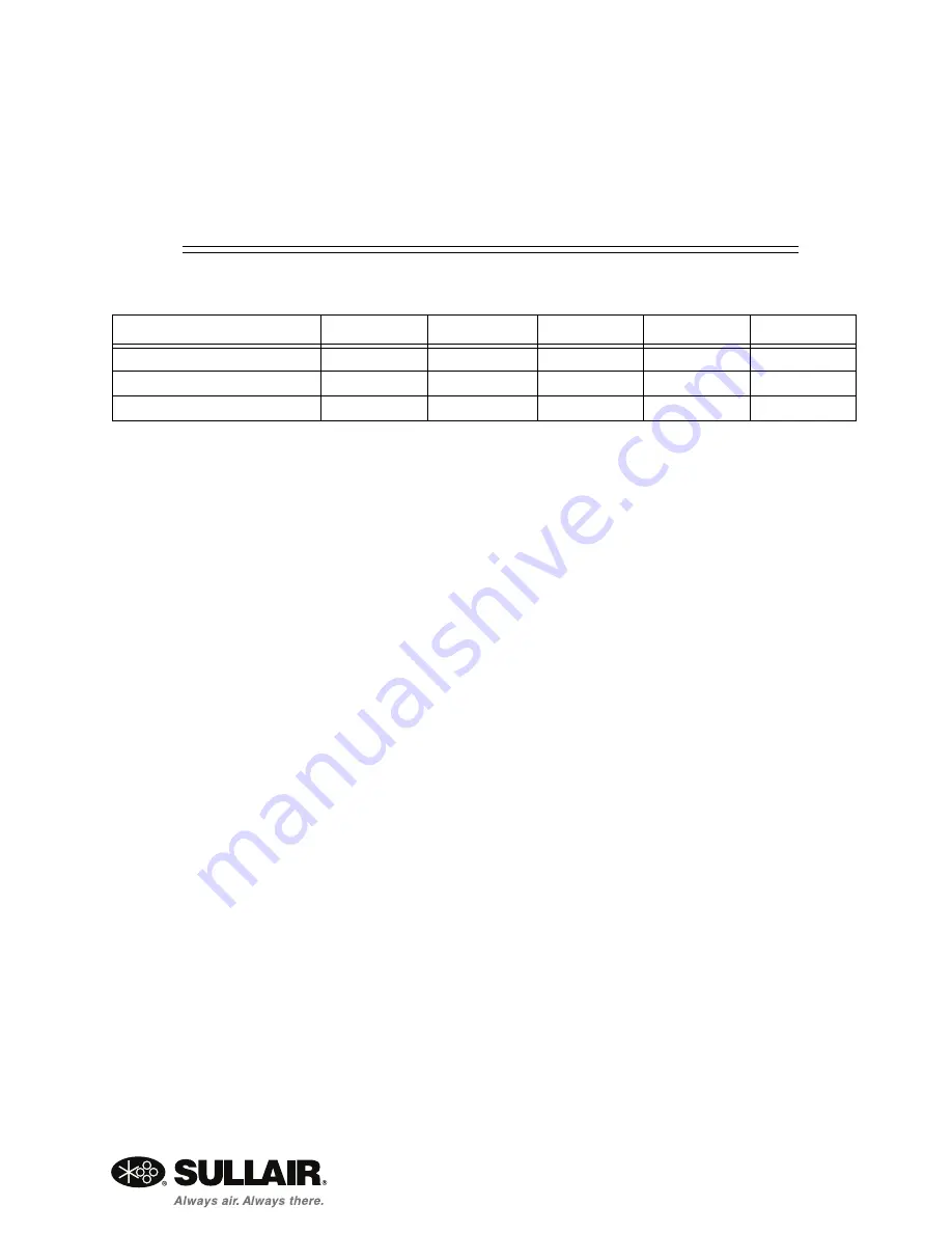
Table 2-1: CONNECTIONS
OWS-88
OWS-210/420
OWS-880
OWS1700
OWS-2100
Condensate Inlet
3 x 1/2”
4 x 1/2”
4 x 1/2”
4 x 1/2”
4 x 1/2”
Water Discharge
1 x 1”
1 x 1”
1 x 1”
1 x 1”
1 x 1”
Oil Discharge
-
-
1 x 1”
1 x 1”
1 x 1”
Summary of Contents for OWS-2I0
Page 4: ...TABLE OF CONTENTS ...
Page 6: ...OIL WATER SEPARATOR SECTION 1 6 1 1 OIL WATER SEPARATOR MODELS Figure 1 1 OWS 88 ...
Page 7: ...SECTION 1 OIL WATER SEPARATOR 7 Figure 1 2 OWS 210 ...
Page 8: ...8 NOTES Figure 1 3 OWS 420 ...
Page 9: ...SECTION 1 OIL WATER SEPARATOR 9 Figure 1 4 OWS 880 ...
Page 10: ...OIL WATER SEPARATOR SECTION 1 10 Figure 1 5 OWS 1700 2100 ...
Page 12: ...OIL WATER SEPARATOR SECTION 2 12 ...
Page 18: ...18 NOTES ...
Page 23: ...NOTES 23 ...


