PRODUCT USER MANUAL
SECTION 3
128
3.62 TROUBLESHOOTING
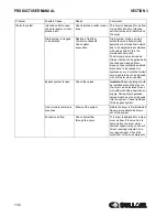
Problem
Possible Cause
Repair
Comments
Dryer is switched on,
indicator light is lit but the
refrigerant compressor
does not turn on.
3-phase dryers: The con-
nection has inverted
phases
Invert two phases
3-phase dryers are equipped with
a phase controller to avoid the
fans from turning in the opposite
direction.
Refrigeration unit is not
functioning
Check refrigeration compres-
sor
Several factors can cause com-
pressor failure. A qualified refrig-
eration technician needs to check
all the electrical and refrigerant
circuit and controls.
The refrigerant high pres-
sure protection has
tripped
The refrigerant safety high
pressure switch has tripped.
The dryer is protected against
excessively high refrigerant pres-
sure. If the condenser efficiency
has reduced, the switch will trip.
In case of water cooled con-
densers, check the water con-
trol valve
1-phase dryer
: manually reset
the switch (green button)
3-phase dryer
: pressure Switch
will automatically reset.
Excessive ambient tem-
perature
Be sure that dryer is working
in temperatures lower than the
design conditions. Designed
conditions and correction fac-
tors are described in this man-
ual .
A high ambient temperature may
cause the refrigerant system to
operate at higher than normal
pressures. Results will be higher
than normal evaporator tempera-
ture. Important: adequate air cir-
culation around the dryer, and
proper ventilation in the equip-
ment room should guarantee a
low enough ambient temperature.
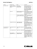
Dryer is switched on,
indicator light is lit but the
refrigerant compressor
does not turn on.
Excessive temperature on
crankcase of compressor.
Allow time to compressor to
cool down. Reason may be a
possible maladjustment of hot
gas bypass or shortage of
refrigerant
Compressor is protected against
overly high temperatures of the
crankcase by a thermal switch
called “Klixon”.
Klixon can be located internally in
the refrigerant compressor or
under the protective cover with
the electrical connections to the
compressor.
Excessive compressed
air inlet temperature.
Be sure that dryer is working
in temperatures lower than
design conditions.
The dryer is designed for working
into calculated conditions (see
description in this manual). If con-
ditions are exceeded, the dryer
will be overflowed, dew point will
go up and protecting devices can
switch off.
Summary of Contents for RD Series
Page 8: ...8 NOTES ...
Page 18: ...RH SERIES HIGH TEMPERATURE SECTION 2 18 2 7 ED RH15 50 02250195 252 R00 ...
Page 20: ...RH SERIES HIGH TEMPERATURE SECTION 2 20 2 8 ED RH75 100 02250195 253 R00 ...
Page 22: ...RH SERIES HIGH TEMPERATURE SECTION 2 22 2 9 ID RH15 50 02250195 252 R00 ...
Page 24: ...RH SERIES HIGH TEMPERATURE SECTION 2 24 2 10 ID RH75 100 02250195 253 ...
Page 26: ...RH SERIES HIGH TEMPERATURE SECTION 2 26 2 11 P I RH15 75 02250195 284 ...
Page 28: ...RH SERIES HIGH TEMPERATURE SECTION 2 28 2 12 P I RH100 02250195 285 ...
Page 30: ...RH SERIES HIGH TEMPERATURE SECTION 2 30 2 13 WIRING DIAGRAM 02250195 303 R00 ...
Page 40: ...40 NOTES ...
Page 50: ...PRODUCT USER MANUAL SECTION 3 50 3 20 ED RN 5 15 02250195 257 R00 ...
Page 52: ...PRODUCT USER MANUAL SECTION 3 52 3 21 ED RN 25 02250195 258 R00 ...
Page 54: ...PRODUCT USER MANUAL SECTION 3 54 3 22 ED RN 35 50 02250195 259 R00 ...
Page 56: ...SECTION 3 PRODUCT USER MANUAL 56 3 23 ED RN 75 02250195 260 R00 ...
Page 58: ...SECTION 3 PRODUCT USER MANUAL 58 3 24 ED RN 100 02250195 260 R00 ...
Page 60: ...SECTION 3 PRODUCT USER MANUAL 60 3 25 ED RN 125 02250195 261 R00 ...
Page 62: ...SECTION 3 PRODUCT USER MANUAL 62 3 26 ED RN 150 02250195 262 R00 ...
Page 64: ...PRODUCT USER MANUAL SECTION 3 64 3 27 ED RN 175 02250195 263 R00 ...
Page 66: ...SECTION 3 PRODUCT USER MANUAL 66 3 28 ED RN 200 02250195 263 R00 ...
Page 68: ...PRODUCT USER MANUAL SECTION 3 68 3 29 ED RN 250 02250195 264 R00 ...
Page 70: ...SECTION 3 PRODUCT USER MANUAL 70 3 30 ED RN 325 230 02250195 264 R00 ...
Page 72: ...PRODUCT USER MANUAL SECTION 3 72 3 31 ED RN 325 460 02250195 264 R00 ...
Page 74: ...SECTION 3 PRODUCT USER MANUAL 74 3 32 ID RN5 15 02250195 257 R00 ...
Page 76: ...PRODUCT USER MANUAL SECTION 3 76 3 33 ID RN25 02250195 258 R00 ...
Page 78: ...PRODUCT USER MANUAL SECTION 3 78 3 34 ID RN35 50 02250195 259 R00 ...
Page 80: ...PRODUCT USER MANUAL SECTION 3 80 3 35 ID RN75 100 02250195 260 ...
Page 82: ...PRODUCT USER MANUAL SECTION 3 82 3 36 ID RN125 02250195 261 ...
Page 84: ...SECTION 3 PRODUCT USER MANUAL 84 3 37 ID RN150 02250195 262 ...
Page 86: ...SECTION 3 PRODUCT USER MANUAL 86 3 38 ID RN175 200 02250195 263 ...
Page 88: ...SECTION 3 PRODUCT USER MANUAL 88 3 39 ID RN250 400 02250195 264 ...
Page 90: ...SECTION 3 PRODUCT USER MANUAL 90 3 40 P I RN5 10 15 25 02250195 288 ...
Page 92: ...SECTION 3 PRODUCT USER MANUAL 92 3 41 P I RN35 75 02250195 289 ...
Page 94: ...SECTION 3 PRODUCT USER MANUAL 94 3 42 P I RN100 200 02250195 290 ...
Page 96: ...SECTION 3 PRODUCT USER MANUAL 96 3 43 P I RN250 325 02250195 291 ...
Page 97: ...PRODUCT USER MANUAL SECTION 3 97 3 44 P I RD400 500 700 850 02250195 293 ...
Page 98: ...SECTION 3 PRODUCT USER MANUAL 98 3 45 P I RD700 850 02250195 294 ...
Page 101: ...101 NOTES ...
Page 102: ...SECTION 3 PRODUCT USER MANUAL 102 3 48 WIRING DIAGRAM RN5 10 15 20 25 02250195 306 ...
Page 104: ...PRODUCT USER MANUAL SECTION 3 104 3 49 WIRING DIAGRAM RN35 50 75 100 02250195 307 ...
Page 106: ...PRODUCT USER MANUAL SECTION 3 106 3 50 WIRING DIAGRAM RN125 150 02250195 308 ...
Page 108: ...PRODUCT USER MANUAL SECTION 3 108 3 51 WIRING DIAGRAM RN175 02250195 309 ...
Page 110: ...PRODUCT USER MANUAL SECTION 3 110 3 52 WIRING DIAGRAM RN200 02250195 310 ...
Page 112: ...PRODUCT USER MANUAL SECTION 3 112 3 53 WIRING DIAGRAM RN250 325 02250195 311 ...
Page 114: ...PRODUCT USER MANUAL SECTION 3 114 3 54 WIRING DIAGRAM RN250 325 230 3 60 A 02250195 973 1 ...
Page 116: ...PRODUCT USER MANUAL SECTION 3 116 3 55 WIRING DIAGRAM RN250 325 230 3 60 A 02250195 973 2 ...
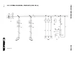
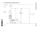
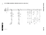
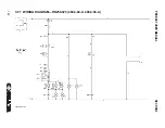
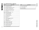
Page 122: ...PRODUCT USER MANUAL SECTION 3 122 3 58 CONTROL CIRCUIT RN250 325 02250195 306 ...
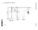
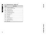
Page 124: ...PRODUCT USER MANUAL SECTION 3 124 3 59 POWER CIRCUIT RN250 325 02250195 306 ...
Page 143: ...SECTION 3 PRODUCT USER MANUAL 143 ...
Page 158: ...158 NOTES ...
Page 166: ...E 680 CONTROLLER FOR REFRIGERANT DRYERS SECTION 4 166 4 3 ED RD400 02250195 264 R00 ...
Page 168: ...E 680 CONTROLLER FOR REFRIGERANT DRYERS SECTION 4 168 4 4 ED RD500 02250195 266 R00 ...
Page 170: ...E 680 CONTROLLER FOR REFRIGERANT DRYERS SECTION 4 170 4 5 ED RD700 02250195 266 R00 ...
Page 174: ...E 680 CONTROLLER FOR REFRIGERANT DRYERS SECTION 4 174 4 7 ED RD850 02250195 266 R00 ...
Page 178: ...E 680 CONTROLLER FOR REFRIGERANT DRYERS SECTION 4 178 4 9 ED RD1000 02250195 266 R00 ...
Page 198: ...SECTION 4 E 680 CONTROLLER FOR REFRIGERANT DRYERS 198 4 19 ID RD400 02250195 264 ...
Page 199: ...SECTION 4 E 680 CONTROLLER FOR REFRIGERANT DRYERS 199 ...
Page 200: ...E 680 CONTROLLER FOR REFRIGERANT DRYERS SECTION 4 200 4 20 ID RD500 850 02250195 266 ...
Page 214: ...E 680 CONTROLLER FOR REFRIGERANT DRYERS SECTION 4 214 4 27 ID RD3800 AIR COOLED 02250195 270 ...
Page 218: ...E 680 CONTROLLER FOR REFRIGERANT DRYERS SECTION 4 218 4 29 P I RD400 02250195 291 ...
Page 220: ...E 680 CONTROLLER FOR REFRIGERANT DRYERS SECTION 4 220 4 30 P I RD500 850 02250195 293 ...
Page 222: ...E 680 CONTROLLER FOR REFRIGERANT DRYERS SECTION 4 222 4 31 P I RD700 850 02250195 294 ...
Page 224: ...E 680 CONTROLLER FOR REFRIGERANT DRYERS SECTION 4 224 4 32 P I RD1000 6000 02250195 297 ...
Page 226: ...E 680 CONTROLLER FOR REFRIGERANT DRYERS SECTION 4 226 4 33 P I RD1000 6000 02250195 298 ...
Page 266: ...266 NOTES ...
Page 267: ...NOTES 267 ...

