SECTION 3
PRODUCT USER MANUAL
129
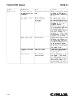
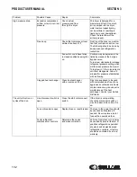
Dryer-on light is lit but
Refrigerant Compressor
does not run.
Clogged condenser fins
or clogged water
condenser.
Possible high crankcase
temperature
Possible loss of phase
Possible low voltage caus-
ing overload trip
Possible failed compres-
sor
Clear fins or water
condenser of all
obstructions.
The clogged fins in the con-
denser will restrict the air pas-
sage and reduce the refrigeration
capacity, causing high tempera-
ture in the evaporator. Same will
occur if water condenser is
clogged with mud or dirt. Air con-
denser and water condenser
should be periodically checked
and cleaned. Protect water circuit
by an adapted filter.
Too much compressed air
flow.
Check actual flow
through the dryer.
This dryer is designed for a maxi-
mum air flow at design condi-
tions. If too much air is pumped
into the dryer, water removal
capacity may not be sufficient,
resulting in liquid carryover down-
stream. Check the rated output
the air compressor.
Faulty electrical wiring
Inspect the circuit
The compressor-on light should
be wired into the refrigerant
compressor circuit. See wiring
diagram in chapter ??rawings?
of this manual.
One electrical protection
has tripped.
Reset the protection or
replace the blown fuse.
The dryer is protected against
high amp draw by fuse and/or
overload relay that can trip in
case of need. Reset or replace
fuse once, but do not persist if it
trips again, request assistance
from a qualified refrigeration con-
tractor.
Dryer-on light is lit but
fan is not running.
Fan has to run if refriger-
ant high pressure reaches
upper set point.
Check that compressed air
flows through the dryer. Check
that fan blades are free to
move. Check the fan pressure
switch.
Fan operates automatically to
keep refrigerant pressure below
the maximum value. The fan can
stop if pressure is under
the recommended setting.
When compressor starts,
it vibrates a lot and
makes mechanical noise.
Compressor is slugging
liquid refrigerant at start-
up.
Be sure the pre-heating period
of at least4 hours is respected
for dryers equipped with a
crankcase heater.
Refrigerant may move between
receivers when refrigerant com-
pressor is stopped and not
heated, especially if stopped for a
long time. This migration may
cause liquid shock (slugging) in
valves specially on large dryers
containing more refrigerant.
Problem
Possible Cause
Repair
Comments
Summary of Contents for RD Series
Page 8: ...8 NOTES ...
Page 18: ...RH SERIES HIGH TEMPERATURE SECTION 2 18 2 7 ED RH15 50 02250195 252 R00 ...
Page 20: ...RH SERIES HIGH TEMPERATURE SECTION 2 20 2 8 ED RH75 100 02250195 253 R00 ...
Page 22: ...RH SERIES HIGH TEMPERATURE SECTION 2 22 2 9 ID RH15 50 02250195 252 R00 ...
Page 24: ...RH SERIES HIGH TEMPERATURE SECTION 2 24 2 10 ID RH75 100 02250195 253 ...
Page 26: ...RH SERIES HIGH TEMPERATURE SECTION 2 26 2 11 P I RH15 75 02250195 284 ...
Page 28: ...RH SERIES HIGH TEMPERATURE SECTION 2 28 2 12 P I RH100 02250195 285 ...
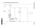
Page 30: ...RH SERIES HIGH TEMPERATURE SECTION 2 30 2 13 WIRING DIAGRAM 02250195 303 R00 ...
Page 40: ...40 NOTES ...
Page 50: ...PRODUCT USER MANUAL SECTION 3 50 3 20 ED RN 5 15 02250195 257 R00 ...
Page 52: ...PRODUCT USER MANUAL SECTION 3 52 3 21 ED RN 25 02250195 258 R00 ...
Page 54: ...PRODUCT USER MANUAL SECTION 3 54 3 22 ED RN 35 50 02250195 259 R00 ...
Page 56: ...SECTION 3 PRODUCT USER MANUAL 56 3 23 ED RN 75 02250195 260 R00 ...
Page 58: ...SECTION 3 PRODUCT USER MANUAL 58 3 24 ED RN 100 02250195 260 R00 ...
Page 60: ...SECTION 3 PRODUCT USER MANUAL 60 3 25 ED RN 125 02250195 261 R00 ...
Page 62: ...SECTION 3 PRODUCT USER MANUAL 62 3 26 ED RN 150 02250195 262 R00 ...
Page 64: ...PRODUCT USER MANUAL SECTION 3 64 3 27 ED RN 175 02250195 263 R00 ...
Page 66: ...SECTION 3 PRODUCT USER MANUAL 66 3 28 ED RN 200 02250195 263 R00 ...
Page 68: ...PRODUCT USER MANUAL SECTION 3 68 3 29 ED RN 250 02250195 264 R00 ...
Page 70: ...SECTION 3 PRODUCT USER MANUAL 70 3 30 ED RN 325 230 02250195 264 R00 ...
Page 72: ...PRODUCT USER MANUAL SECTION 3 72 3 31 ED RN 325 460 02250195 264 R00 ...
Page 74: ...SECTION 3 PRODUCT USER MANUAL 74 3 32 ID RN5 15 02250195 257 R00 ...
Page 76: ...PRODUCT USER MANUAL SECTION 3 76 3 33 ID RN25 02250195 258 R00 ...
Page 78: ...PRODUCT USER MANUAL SECTION 3 78 3 34 ID RN35 50 02250195 259 R00 ...
Page 80: ...PRODUCT USER MANUAL SECTION 3 80 3 35 ID RN75 100 02250195 260 ...
Page 82: ...PRODUCT USER MANUAL SECTION 3 82 3 36 ID RN125 02250195 261 ...
Page 84: ...SECTION 3 PRODUCT USER MANUAL 84 3 37 ID RN150 02250195 262 ...
Page 86: ...SECTION 3 PRODUCT USER MANUAL 86 3 38 ID RN175 200 02250195 263 ...
Page 88: ...SECTION 3 PRODUCT USER MANUAL 88 3 39 ID RN250 400 02250195 264 ...
Page 90: ...SECTION 3 PRODUCT USER MANUAL 90 3 40 P I RN5 10 15 25 02250195 288 ...
Page 92: ...SECTION 3 PRODUCT USER MANUAL 92 3 41 P I RN35 75 02250195 289 ...
Page 94: ...SECTION 3 PRODUCT USER MANUAL 94 3 42 P I RN100 200 02250195 290 ...
Page 96: ...SECTION 3 PRODUCT USER MANUAL 96 3 43 P I RN250 325 02250195 291 ...
Page 97: ...PRODUCT USER MANUAL SECTION 3 97 3 44 P I RD400 500 700 850 02250195 293 ...
Page 98: ...SECTION 3 PRODUCT USER MANUAL 98 3 45 P I RD700 850 02250195 294 ...
Page 101: ...101 NOTES ...
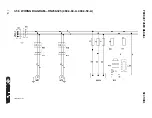
Page 102: ...SECTION 3 PRODUCT USER MANUAL 102 3 48 WIRING DIAGRAM RN5 10 15 20 25 02250195 306 ...
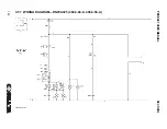
Page 104: ...PRODUCT USER MANUAL SECTION 3 104 3 49 WIRING DIAGRAM RN35 50 75 100 02250195 307 ...
Page 106: ...PRODUCT USER MANUAL SECTION 3 106 3 50 WIRING DIAGRAM RN125 150 02250195 308 ...
Page 108: ...PRODUCT USER MANUAL SECTION 3 108 3 51 WIRING DIAGRAM RN175 02250195 309 ...
Page 110: ...PRODUCT USER MANUAL SECTION 3 110 3 52 WIRING DIAGRAM RN200 02250195 310 ...
Page 112: ...PRODUCT USER MANUAL SECTION 3 112 3 53 WIRING DIAGRAM RN250 325 02250195 311 ...
Page 114: ...PRODUCT USER MANUAL SECTION 3 114 3 54 WIRING DIAGRAM RN250 325 230 3 60 A 02250195 973 1 ...
Page 116: ...PRODUCT USER MANUAL SECTION 3 116 3 55 WIRING DIAGRAM RN250 325 230 3 60 A 02250195 973 2 ...
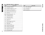
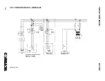
Page 122: ...PRODUCT USER MANUAL SECTION 3 122 3 58 CONTROL CIRCUIT RN250 325 02250195 306 ...
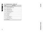
Page 124: ...PRODUCT USER MANUAL SECTION 3 124 3 59 POWER CIRCUIT RN250 325 02250195 306 ...
Page 143: ...SECTION 3 PRODUCT USER MANUAL 143 ...
Page 158: ...158 NOTES ...
Page 166: ...E 680 CONTROLLER FOR REFRIGERANT DRYERS SECTION 4 166 4 3 ED RD400 02250195 264 R00 ...
Page 168: ...E 680 CONTROLLER FOR REFRIGERANT DRYERS SECTION 4 168 4 4 ED RD500 02250195 266 R00 ...
Page 170: ...E 680 CONTROLLER FOR REFRIGERANT DRYERS SECTION 4 170 4 5 ED RD700 02250195 266 R00 ...
Page 174: ...E 680 CONTROLLER FOR REFRIGERANT DRYERS SECTION 4 174 4 7 ED RD850 02250195 266 R00 ...
Page 178: ...E 680 CONTROLLER FOR REFRIGERANT DRYERS SECTION 4 178 4 9 ED RD1000 02250195 266 R00 ...
Page 198: ...SECTION 4 E 680 CONTROLLER FOR REFRIGERANT DRYERS 198 4 19 ID RD400 02250195 264 ...
Page 199: ...SECTION 4 E 680 CONTROLLER FOR REFRIGERANT DRYERS 199 ...
Page 200: ...E 680 CONTROLLER FOR REFRIGERANT DRYERS SECTION 4 200 4 20 ID RD500 850 02250195 266 ...
Page 214: ...E 680 CONTROLLER FOR REFRIGERANT DRYERS SECTION 4 214 4 27 ID RD3800 AIR COOLED 02250195 270 ...
Page 218: ...E 680 CONTROLLER FOR REFRIGERANT DRYERS SECTION 4 218 4 29 P I RD400 02250195 291 ...
Page 220: ...E 680 CONTROLLER FOR REFRIGERANT DRYERS SECTION 4 220 4 30 P I RD500 850 02250195 293 ...
Page 222: ...E 680 CONTROLLER FOR REFRIGERANT DRYERS SECTION 4 222 4 31 P I RD700 850 02250195 294 ...
Page 224: ...E 680 CONTROLLER FOR REFRIGERANT DRYERS SECTION 4 224 4 32 P I RD1000 6000 02250195 297 ...
Page 226: ...E 680 CONTROLLER FOR REFRIGERANT DRYERS SECTION 4 226 4 33 P I RD1000 6000 02250195 298 ...
Page 266: ...266 NOTES ...
Page 267: ...NOTES 267 ...


