SECTION 2
RH SERIES—HIGH TEMPERATURE
33
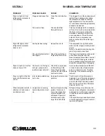
Dryer-on light is lit but
refrigerant compressor is
not operating
Clogged condenser fins
Clear fins of all obstruc-
tions
The clogged fins in the condenser will
restrict the air passage and reduce
the refrigeration capacity, causing
high temperature in the evaporator.
Air condensers should be periodically
checked and cleaned.
Too much air flow
Check actual flow
through the dryer
This dryer is designed for a maximum
air flow. If too much air is pumped into
the dryer, water removal capacity
decreases, resulting in liquid carry-
over downstream. Check the rated
output of the air compressor and
make sure that it matches the dryer
capacity.
Dryer-ON light is lit but
refrigerant compressor
does not run
Faulty electrical wiring
Inspect the circuit
The compressor-on light should be
wired into the refrigerant compressor
circuit.
Refer to the electrical and wiring dia-
gram for proper connections.
One electrical protection
has tripped
Reset the protection or
replace the blown fuse
The dryer is protected by a fuse and/
or overload relay that can trip.
Reset or replace blown fuse once, but
do not insist if it trips again. Instead
have a qualified refrigerant technician
check the complete dryer thoroughly.
Dryer-on light is lit but fan
does not come ON
Fan has to run if refriger-
ant high pressure has
reached upper set point
Check the compressed
air flows through the
dryer. Check to make
sure that the fan blades
are free to rotate.
Fan is automatically turned ON/OFF
in order to keep the refrigerant pres-
sure to a minimum value. The fans
might stop if the pressure setting is
incorrect
Dryer on light is lit but fan
motor of aftercooler does
not run
Inlet air temperature may
be too low
Increase the inlet air tem-
perature
The fan motor of the aftercooler is
designed to run if the inlet air temper-
ature is equal or greater then 95F. In
case it is less then that temperature
then the fan motor of the aftercooler
does not start to run.
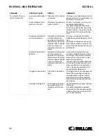
When compressor starts, it
vibrates a lot and makes
mechanical noise
Compressor is sucking
liquid refrigerant at start
up.
Be sure that pre-heating
period of minimum 4
hours has elapsed for
dryers equipped with
crankcase heater (all
models equal to and
larger than 250CFM)
Refrigerant may move between the
receiver when refrigerant compressor
is stopped and not heated, especially
if it has been non-operational for a
long time
This migration may cause liquid shock
in valves specially on dryers contain-
ing more refrigerant
PROBLEM
POSSIBLE CAUSE
REPAIR
COMMENTS
Summary of Contents for RD Series
Page 8: ...8 NOTES ...
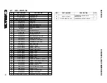
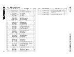
Page 18: ...RH SERIES HIGH TEMPERATURE SECTION 2 18 2 7 ED RH15 50 02250195 252 R00 ...
Page 20: ...RH SERIES HIGH TEMPERATURE SECTION 2 20 2 8 ED RH75 100 02250195 253 R00 ...
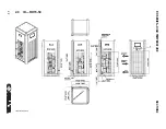
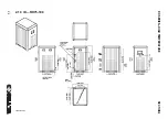
Page 22: ...RH SERIES HIGH TEMPERATURE SECTION 2 22 2 9 ID RH15 50 02250195 252 R00 ...
Page 24: ...RH SERIES HIGH TEMPERATURE SECTION 2 24 2 10 ID RH75 100 02250195 253 ...
Page 26: ...RH SERIES HIGH TEMPERATURE SECTION 2 26 2 11 P I RH15 75 02250195 284 ...
Page 28: ...RH SERIES HIGH TEMPERATURE SECTION 2 28 2 12 P I RH100 02250195 285 ...
Page 30: ...RH SERIES HIGH TEMPERATURE SECTION 2 30 2 13 WIRING DIAGRAM 02250195 303 R00 ...
Page 40: ...40 NOTES ...
Page 50: ...PRODUCT USER MANUAL SECTION 3 50 3 20 ED RN 5 15 02250195 257 R00 ...
Page 52: ...PRODUCT USER MANUAL SECTION 3 52 3 21 ED RN 25 02250195 258 R00 ...
Page 54: ...PRODUCT USER MANUAL SECTION 3 54 3 22 ED RN 35 50 02250195 259 R00 ...
Page 56: ...SECTION 3 PRODUCT USER MANUAL 56 3 23 ED RN 75 02250195 260 R00 ...
Page 58: ...SECTION 3 PRODUCT USER MANUAL 58 3 24 ED RN 100 02250195 260 R00 ...
Page 60: ...SECTION 3 PRODUCT USER MANUAL 60 3 25 ED RN 125 02250195 261 R00 ...
Page 62: ...SECTION 3 PRODUCT USER MANUAL 62 3 26 ED RN 150 02250195 262 R00 ...
Page 64: ...PRODUCT USER MANUAL SECTION 3 64 3 27 ED RN 175 02250195 263 R00 ...
Page 66: ...SECTION 3 PRODUCT USER MANUAL 66 3 28 ED RN 200 02250195 263 R00 ...
Page 68: ...PRODUCT USER MANUAL SECTION 3 68 3 29 ED RN 250 02250195 264 R00 ...
Page 70: ...SECTION 3 PRODUCT USER MANUAL 70 3 30 ED RN 325 230 02250195 264 R00 ...
Page 72: ...PRODUCT USER MANUAL SECTION 3 72 3 31 ED RN 325 460 02250195 264 R00 ...
Page 74: ...SECTION 3 PRODUCT USER MANUAL 74 3 32 ID RN5 15 02250195 257 R00 ...
Page 76: ...PRODUCT USER MANUAL SECTION 3 76 3 33 ID RN25 02250195 258 R00 ...
Page 78: ...PRODUCT USER MANUAL SECTION 3 78 3 34 ID RN35 50 02250195 259 R00 ...
Page 80: ...PRODUCT USER MANUAL SECTION 3 80 3 35 ID RN75 100 02250195 260 ...
Page 82: ...PRODUCT USER MANUAL SECTION 3 82 3 36 ID RN125 02250195 261 ...
Page 84: ...SECTION 3 PRODUCT USER MANUAL 84 3 37 ID RN150 02250195 262 ...
Page 86: ...SECTION 3 PRODUCT USER MANUAL 86 3 38 ID RN175 200 02250195 263 ...
Page 88: ...SECTION 3 PRODUCT USER MANUAL 88 3 39 ID RN250 400 02250195 264 ...
Page 90: ...SECTION 3 PRODUCT USER MANUAL 90 3 40 P I RN5 10 15 25 02250195 288 ...
Page 92: ...SECTION 3 PRODUCT USER MANUAL 92 3 41 P I RN35 75 02250195 289 ...
Page 94: ...SECTION 3 PRODUCT USER MANUAL 94 3 42 P I RN100 200 02250195 290 ...
Page 96: ...SECTION 3 PRODUCT USER MANUAL 96 3 43 P I RN250 325 02250195 291 ...
Page 97: ...PRODUCT USER MANUAL SECTION 3 97 3 44 P I RD400 500 700 850 02250195 293 ...
Page 98: ...SECTION 3 PRODUCT USER MANUAL 98 3 45 P I RD700 850 02250195 294 ...
Page 101: ...101 NOTES ...
Page 102: ...SECTION 3 PRODUCT USER MANUAL 102 3 48 WIRING DIAGRAM RN5 10 15 20 25 02250195 306 ...
Page 104: ...PRODUCT USER MANUAL SECTION 3 104 3 49 WIRING DIAGRAM RN35 50 75 100 02250195 307 ...
Page 106: ...PRODUCT USER MANUAL SECTION 3 106 3 50 WIRING DIAGRAM RN125 150 02250195 308 ...
Page 108: ...PRODUCT USER MANUAL SECTION 3 108 3 51 WIRING DIAGRAM RN175 02250195 309 ...
Page 110: ...PRODUCT USER MANUAL SECTION 3 110 3 52 WIRING DIAGRAM RN200 02250195 310 ...
Page 112: ...PRODUCT USER MANUAL SECTION 3 112 3 53 WIRING DIAGRAM RN250 325 02250195 311 ...
Page 114: ...PRODUCT USER MANUAL SECTION 3 114 3 54 WIRING DIAGRAM RN250 325 230 3 60 A 02250195 973 1 ...
Page 116: ...PRODUCT USER MANUAL SECTION 3 116 3 55 WIRING DIAGRAM RN250 325 230 3 60 A 02250195 973 2 ...
Page 122: ...PRODUCT USER MANUAL SECTION 3 122 3 58 CONTROL CIRCUIT RN250 325 02250195 306 ...
Page 124: ...PRODUCT USER MANUAL SECTION 3 124 3 59 POWER CIRCUIT RN250 325 02250195 306 ...
Page 143: ...SECTION 3 PRODUCT USER MANUAL 143 ...
Page 158: ...158 NOTES ...
Page 166: ...E 680 CONTROLLER FOR REFRIGERANT DRYERS SECTION 4 166 4 3 ED RD400 02250195 264 R00 ...
Page 168: ...E 680 CONTROLLER FOR REFRIGERANT DRYERS SECTION 4 168 4 4 ED RD500 02250195 266 R00 ...
Page 170: ...E 680 CONTROLLER FOR REFRIGERANT DRYERS SECTION 4 170 4 5 ED RD700 02250195 266 R00 ...
Page 174: ...E 680 CONTROLLER FOR REFRIGERANT DRYERS SECTION 4 174 4 7 ED RD850 02250195 266 R00 ...
Page 178: ...E 680 CONTROLLER FOR REFRIGERANT DRYERS SECTION 4 178 4 9 ED RD1000 02250195 266 R00 ...
Page 198: ...SECTION 4 E 680 CONTROLLER FOR REFRIGERANT DRYERS 198 4 19 ID RD400 02250195 264 ...
Page 199: ...SECTION 4 E 680 CONTROLLER FOR REFRIGERANT DRYERS 199 ...
Page 200: ...E 680 CONTROLLER FOR REFRIGERANT DRYERS SECTION 4 200 4 20 ID RD500 850 02250195 266 ...
Page 214: ...E 680 CONTROLLER FOR REFRIGERANT DRYERS SECTION 4 214 4 27 ID RD3800 AIR COOLED 02250195 270 ...
Page 218: ...E 680 CONTROLLER FOR REFRIGERANT DRYERS SECTION 4 218 4 29 P I RD400 02250195 291 ...
Page 220: ...E 680 CONTROLLER FOR REFRIGERANT DRYERS SECTION 4 220 4 30 P I RD500 850 02250195 293 ...
Page 222: ...E 680 CONTROLLER FOR REFRIGERANT DRYERS SECTION 4 222 4 31 P I RD700 850 02250195 294 ...
Page 224: ...E 680 CONTROLLER FOR REFRIGERANT DRYERS SECTION 4 224 4 32 P I RD1000 6000 02250195 297 ...
Page 226: ...E 680 CONTROLLER FOR REFRIGERANT DRYERS SECTION 4 226 4 33 P I RD1000 6000 02250195 298 ...
Page 266: ...266 NOTES ...
Page 267: ...NOTES 267 ...

