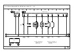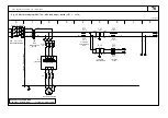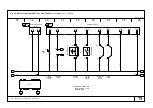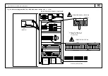
85
Code: 02250144
--
517 SRV
--
250 --- SRV
--
2400
English --
Legend
i.
ATTENTION!
Never pass compressed air through the dryer when it is stopped.
Always start the dryer 5 minutes before slowly opening the air
inlet valve. If the airflow is to bestopped only switch the dryer
off after closing the air inlet.
l.
ATTENTION:
Hot and moving parts enclosed, disconnect the
mains supply before removing this cover.
m.
WARNING:
Risk of electric shock can cause injury or death.
Disconnect all remote electric power supplies before servicing.
n.
BSPP pipe threads
use supplied adapters
o.
Air ---cooled versions:
See para. 3.2.
p.
ATTENTION
1 Fully drain the piping before connectingthis unit to theexter-
nal water piping (cold water, make up water, ect.).
2 Fitting of a standard strainer is also strongly recommended
on the inlet water piping.
q.
Water ---cooled versions:
See para. 3.2.
DRAWINGS
1. MC
--
1
compressor
2.
refrigerant condenser
3. EV1
fan motor
EV2
inverter fan motor
4.
evaporator
5.
separator
7.
by---pass capillary
8.
refrigerant filter
9. YV2
hot gas by
--
pass electrovalve
9a. YV1
start---up by
--
pass electrovalve
9b. YV3
thermostatic interception electrovalve
10.
air---air heat exchanger
11.
insulation
12. PV
fan pressure switch
14. QS
main disconnector switch
15. HP
high pressure switch
18.
high pressure manometer
19.
thermostatic valve
21.
distribution capillary
25.
thermometer sensor pocket
27.
gas charge point
29.
inverter cooling fan
28.
water pressostatic valve
30. QF1
inverter automatic switch
30a.QF2
fan motor automatic switch
31. KM1
fan motor contactor
33. TC1
auxiliary transformer 230V
34. TC2
auxiliary transformer 24V
35.
power cable inlet
36.
remote control cable entry point
T0
dew point temperature sensor
T1
evaporation temperature sensor
T2
refrigerant suction temperature sensor
T3
ambient temperature sensor
T4
air inlet temperature sensor
P1
low pressure transmitter
FU1
--
2 auxiliary transformer fuse
FU3
--
4 auxiliary fuse 230V
FU5
--
6 auxiliary fuse 24V
KA1
high pressure alarm relay
YV4
condensate drain valve (not installed if
electronic drain is foreseen)
A1
electronic control
A2
inverter
A3
display card
J1..J15 control connectors
QF
residual current circuit---breaker
(by installer)
LABELS
a.
S
Model
S
Serial No.
S
Low/High side refrigeration
circuit design pressure
S
Max air pressure
S
Max compressed air inlet
S
Min. ambient
Max ambient
S
Power supply
Electrical diagram no.
S
Oil
S
Min. circuit ampacity
S
Max protective device rating
S
Compressor
S
Fan 1
S
Fan 2
S
Max cooling water pressure
S
Min. cooling water pressure
S
Refrigerant
S
Weight
b. QUALITY CHECKED INSPECTOR N. 302
c. See Chapter 2
d. Air inlet
e. Air outlet
d1. Water inlet
e1. Water outlet
f.
ATTENTION:
components under power.
g.
ATTENTION: SCHRADER VALVE
1 This unit is equipped with refrigerant as for quantity and kind clearly shown
in operating manual and with identification label.
2 Any ordinary test and / or refrigerant recharge by means of connections can
take place only after refrigerant evacuation. The evacuation must be pro-
portional to dimensions and length of the connections used. The use of the
valve can be justified only when the dryer is not in working order.
3 During the unit guarantee period, the Schrader valve can be used by autho-
rized staff only, otherwise any damage caused by a wrong refrigerant
recharge will not be under warranty.
h. Condensate drain connection


