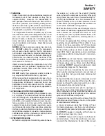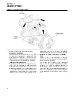
or swinging of the compressor once it has been lift-
ed clear of the ground.
F. DO NOT
attempt to lift in high winds.
G.
Keep all personnel out from under and away
from the compressor whenever it is suspended.
H.
Lift compressor no higher than necessary.
I.
Keep lift operator in constant attendance whenev-
er compressor is suspended.
J.
Set compressor down only on a level surface
capable of safely supporting at least its weight and
its loading unit.
K.
When moving compressors by forklift truck, uti-
lize fork pockets if provided. Otherwise, utilize pal-
let if provided. If neither fork pockets or pallet are
provided, then make sure compressor is secure
and well balanced on forks before attempting to
raise or transport it any significant distance.
L.
Make sure forklift truck forks are fully engaged
and tipped back prior to lifting or transporting the
compressor.
M.
Forklift no higher than necessary to clear obsta-
cles at floor level and transport and corner at mini-
mum practical speeds.
N.
Make sure pallet-mounted compressors are firm-
ly bolted or otherwise secured to the pallet prior to
attempting to forklift or transport them.
NEVER
attempt to forklift a compressor that is not secured
to its pallet, as uneven floors or sudden stops may
cause the compressor to tumble off, possibly caus-
ing serious injury or property damage in the
process.
O. DO NOT
use the lifting eye bolt on the compres-
sor motor, if supplied, to lift the entire compressor
package.
1.10 ENTRAPMENT
A.
If the compressor enclosure is large enough to
hold a person and if it is necessary to enter it to per-
form service adjustments, inform other personnel
before doing so, or else secure and tag the access
door in the open position to avoid the possibility of
others closing and possibly latching the door with
personnel inside.
B.
Make sure all personnel are out of compressor
before closing and latching enclosure doors.
Section 1
SAFETY
4
Summary of Contents for TS-32S
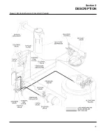
Page 16: ...Section 2 DESCRIPTION 10 Figure 2 3A Compressor Cooling and Lubrication System Air cooled...
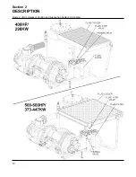
Page 17: ...Section 2 DESCRIPTION 11 Figure 2 3B Compressor Cooling and Lubrication System Water cooled...
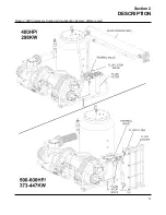
Page 18: ...Section 2 DESCRIPTION 12 Figure 2 4A Compressor Discharge System Air cooled...
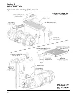
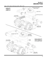
Page 19: ...Section 2 DESCRIPTION 13 Figure 2 4B Compressor Discharge System Water cooled...
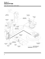
Page 20: ...Section 2 DESCRIPTION 14 Figure 2 5A Control System START Typical...
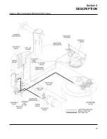
Page 21: ...Section 2 DESCRIPTION 15 Figure 2 5B Control System MODULATION Typical...
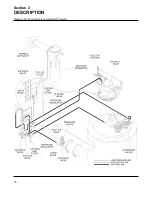
Page 22: ...Section 2 DESCRIPTION 16 Figure 2 5C Control System UNLOAD Typical...
Page 23: ...Section 2 DESCRIPTION 17 Figure 2 5D Control System FULL LOAD Typical...
Page 27: ...Section 3 SPECIFICATIONS 21 NOTES...
Page 40: ...34 NOTES...
Page 48: ...42 NOTES...
Page 60: ...54 NOTES...
Page 63: ...57 NOTES...
Page 72: ...Section 8 ILLUSTRATIONS AND PARTS LIST 66 8 5 AIR INLET SYSTEM 02250135 499R01...
Page 114: ...Section 8 ILLUSTRATIONS AND PARTS LIST 108 02250135 534R03 8 20 SUMP AND PARTS...
Page 116: ...Section 8 ILLUSTRATIONS AND PARTS LIST 110 02250135 534R03 8 20 SUMP AND PARTS...
Page 118: ...Section 8 ILLUSTRATIONS AND PARTS LIST 112 02250134 158R00 8 21 SULLICON CONTROL...
Page 120: ...Section 8 ILLUSTRATIONS AND PARTS LIST 114 8 22 COMPRESSOR SPIRIAL VALVE ACTUATOR...
Page 124: ...Section 8 ILLUSTRATIONS AND PARTS LIST 118 02250135 643R05 8 24 PNEUMATIC CONTROLS...
Page 126: ...Section 8 ILLUSTRATIONS AND PARTS LIST 120 02250135 643R05 8 24 PNEUMATIC CONTROLS...
Page 128: ...Section 8 ILLUSTRATIONS AND PARTS LIST 122 02250135 643R05 8 24 PNEUMATIC CONTROLS...
Page 134: ...Section 8 ILLUSTRATIONS AND PARTS LIST 128 8 27 CONTROL BOX WYE DELTA TYPICAL 02250122 516R08...
Page 140: ...Section 8 ILLUSTRATIONS AND PARTS LIST 134 02250133 674R04 8 30 ENCLOSURE AIR COOLED...
Page 142: ...Section 8 ILLUSTRATIONS AND PARTS LIST 136 02250133 674R04 8 30 ENCLOSURE AIR COOLED...
Page 144: ...Section 8 ILLUSTRATIONS AND PARTS LIST 138 02250133 675R04 8 31 ENCLOSURE WATER COOLED...
Page 146: ...Section 8 ILLUSTRATIONS AND PARTS LIST 140 02250133 675R04 8 31 ENCLOSURE WATER COOLED...
Page 148: ...Section 8 ILLUSTRATIONS AND PARTS LIST 142 8 32 DECALS...
Page 150: ...Section 8 ILLUSTRATIONS AND PARTS LIST 144 8 32 DECALS...
Page 152: ...Section 8 ILLUSTRATIONS AND PARTS LIST 146 8 32 DECALS...
Page 154: ...Section 8 ILLUSTRATIONS AND PARTS LIST 148 8 33 DECAL LOCATIONS...
Page 156: ...Section 8 ILLUSTRATIONS AND PARTS LIST 150 8 34 DECAL LOCATIONS AIR COOLED ENCLOSURE TYPICAL...
Page 158: ...Section 8 ILLUSTRATIONS AND PARTS LIST 152 8 35 DECAL LOCATIONS WATER COOLED ENCLOSURE TYPICAL...
Page 160: ...Section 8 ILLUSTRATIONS AND PARTS LIST 154 8 36 DECAL LOCATIONS CONTROL BOX...
Page 162: ...Section 8 ILLUSTRATIONS AND PARTS LIST 156 8 37 DECAL LOCATIONS AFTER COOLER...
Page 171: ...NOTES...


