Section 8
ILLUSTRATIONS AND PARTS LIST
115
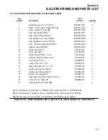
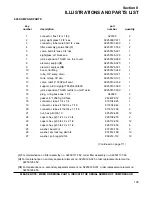
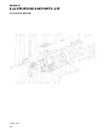
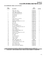
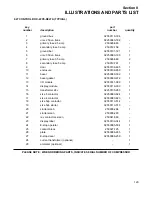
8.22 COMPRESSOR SPIRIAL VALVE ACTUATOR
key
part
number
description
number
quantity
1
shaft, valve - direct
250030-981
1
•shaft, valve - geared
250030-982
1
2
valve, weight counterbalance
250016-193
1
3
capscrew, socket 3/8”-16 x 1”
828906-100
2
4
ring, retaining
499068-005
1
5
bearing, ball
499002-207
1
6
seal, lip
250016-200
1
7
screw, set 1/2”-13 x 1.62 br
250024-465
1
8
adapter, air cylinder
250016-182
1
9
capscrew, ferry head 1/2”-13 x 1 1/2”
828408-150
6
10
guide, rack
250016-199
1
11
gear, pinion
250016-196
1
12
indicator, actuator
250030-983
1
13
pin, roll unfinished 1/4”x 1”
827404-100
1
14
capscrew, hex head gr8 1/4”-20 x 1/2”
828204-050
4
15
cover, adapter
250016-195
1
16
washer, regular #8
838201-045
6
17
screw, machine rod #8-32 x 1/2”
831601-050
6
18
mount, air cylinder
250016-188
1
19
capscrew, ferry head 1/2”-18 x 1 1/4”
828405-125
3
20
spring, seal 2 1/4”
250016-394
1
21
rack, gear
250016-197
1
22
nut, hex jam 3/8”-16
824906-227
1
23
shaft, air cylinder
250016-194
1
24
cylinder, air
(I)
250016-183
1
25
orifice, .062 x .25m x .25f
028831
1
26
nut, hex unfinished 1/2”-13
824208-448
1
27
screw, machine hex 1/4”-20 x 1 3/4”
830104-175
1
28
nut, hex jam 1/4”-20
824904-164
1
29
decal, warning actuator
250029-836
1
30
decal, actuator valve positioning
250029-784
1
(I)
For maintenance on air cylinder no. 250016-183, order diaphragm repair kit no. 608311-001.
PLEASE NOTE: WHEN ORDERING PARTS, INDICATE SERIAL NUMBER OF COMPRESSOR
Summary of Contents for TS-32S
Page 16: ...Section 2 DESCRIPTION 10 Figure 2 3A Compressor Cooling and Lubrication System Air cooled...
Page 17: ...Section 2 DESCRIPTION 11 Figure 2 3B Compressor Cooling and Lubrication System Water cooled...
Page 18: ...Section 2 DESCRIPTION 12 Figure 2 4A Compressor Discharge System Air cooled...
Page 19: ...Section 2 DESCRIPTION 13 Figure 2 4B Compressor Discharge System Water cooled...
Page 20: ...Section 2 DESCRIPTION 14 Figure 2 5A Control System START Typical...
Page 21: ...Section 2 DESCRIPTION 15 Figure 2 5B Control System MODULATION Typical...
Page 22: ...Section 2 DESCRIPTION 16 Figure 2 5C Control System UNLOAD Typical...
Page 23: ...Section 2 DESCRIPTION 17 Figure 2 5D Control System FULL LOAD Typical...
Page 27: ...Section 3 SPECIFICATIONS 21 NOTES...
Page 40: ...34 NOTES...
Page 48: ...42 NOTES...
Page 60: ...54 NOTES...
Page 63: ...57 NOTES...
Page 72: ...Section 8 ILLUSTRATIONS AND PARTS LIST 66 8 5 AIR INLET SYSTEM 02250135 499R01...
Page 114: ...Section 8 ILLUSTRATIONS AND PARTS LIST 108 02250135 534R03 8 20 SUMP AND PARTS...
Page 116: ...Section 8 ILLUSTRATIONS AND PARTS LIST 110 02250135 534R03 8 20 SUMP AND PARTS...
Page 118: ...Section 8 ILLUSTRATIONS AND PARTS LIST 112 02250134 158R00 8 21 SULLICON CONTROL...
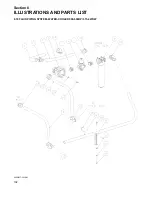
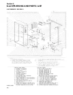
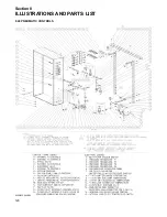
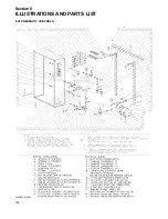
Page 120: ...Section 8 ILLUSTRATIONS AND PARTS LIST 114 8 22 COMPRESSOR SPIRIAL VALVE ACTUATOR...
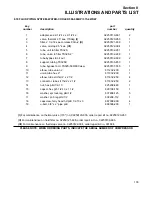
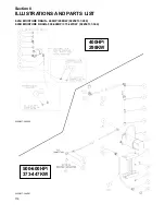
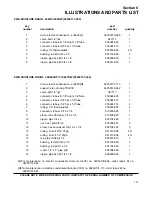
Page 124: ...Section 8 ILLUSTRATIONS AND PARTS LIST 118 02250135 643R05 8 24 PNEUMATIC CONTROLS...
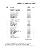
Page 126: ...Section 8 ILLUSTRATIONS AND PARTS LIST 120 02250135 643R05 8 24 PNEUMATIC CONTROLS...
Page 128: ...Section 8 ILLUSTRATIONS AND PARTS LIST 122 02250135 643R05 8 24 PNEUMATIC CONTROLS...
Page 134: ...Section 8 ILLUSTRATIONS AND PARTS LIST 128 8 27 CONTROL BOX WYE DELTA TYPICAL 02250122 516R08...
Page 140: ...Section 8 ILLUSTRATIONS AND PARTS LIST 134 02250133 674R04 8 30 ENCLOSURE AIR COOLED...
Page 142: ...Section 8 ILLUSTRATIONS AND PARTS LIST 136 02250133 674R04 8 30 ENCLOSURE AIR COOLED...
Page 144: ...Section 8 ILLUSTRATIONS AND PARTS LIST 138 02250133 675R04 8 31 ENCLOSURE WATER COOLED...
Page 146: ...Section 8 ILLUSTRATIONS AND PARTS LIST 140 02250133 675R04 8 31 ENCLOSURE WATER COOLED...
Page 148: ...Section 8 ILLUSTRATIONS AND PARTS LIST 142 8 32 DECALS...
Page 150: ...Section 8 ILLUSTRATIONS AND PARTS LIST 144 8 32 DECALS...
Page 152: ...Section 8 ILLUSTRATIONS AND PARTS LIST 146 8 32 DECALS...
Page 154: ...Section 8 ILLUSTRATIONS AND PARTS LIST 148 8 33 DECAL LOCATIONS...
Page 156: ...Section 8 ILLUSTRATIONS AND PARTS LIST 150 8 34 DECAL LOCATIONS AIR COOLED ENCLOSURE TYPICAL...
Page 158: ...Section 8 ILLUSTRATIONS AND PARTS LIST 152 8 35 DECAL LOCATIONS WATER COOLED ENCLOSURE TYPICAL...
Page 160: ...Section 8 ILLUSTRATIONS AND PARTS LIST 154 8 36 DECAL LOCATIONS CONTROL BOX...
Page 162: ...Section 8 ILLUSTRATIONS AND PARTS LIST 156 8 37 DECAL LOCATIONS AFTER COOLER...
Page 171: ...NOTES...

