Section 8
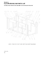
ILLUSTRATIONS AND PARTS LIST
119
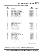
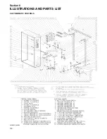
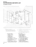
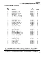
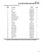
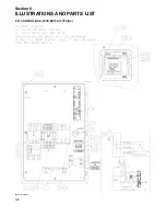
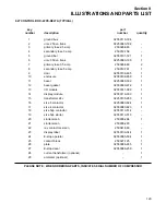
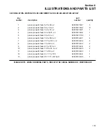
8.24 PNEUMATIC CONTROLS
key
part
number
description
number
quantity
1
locknut, n4 conduit sealing
02250071-362
8
2
grip, cord n4 .125 -.187 x 1/2”
02250071-379
4
3
grip, cord n4 .250-.375 x 1/2”
02250071-381
6
4
switch, vacuum 22”wc n4 6ft cable 5a
02250078-249
1
5
transducer, pressure 0-25psi 1-5vdc n4
02250078-933
4
6
valve, pressure relief 1/2”npt-150 psig
02250092-138
1
7
orifice, .031” x .25m x .25m nptf -
02250101-191
1
8
support, bracket transducer mounting
02250110-132
1
9
valve, check 1/4”nptf viton seat
02250110-557
2
10
filter, control air 1/4”npt
(I)
02250112-032
2
11
gauge, air press 2 1/2” 0-200 psi
02250117-009
2
12
valve, solenoid 3wno 1/4 235# n4
(II)
02250125-657
2
13
valve, solenoid 2wnc 1/4 150# n4 +
(III)
02250125-679
2
14
support, str box ls20s ac
02250127-380
2
15
channel, ctl tubing supt
02250127-559
1
16
angle, support
02250133-550
2
17
bracket, support
02250133-551
1
18
bracket, supt
02250133-552
1
19
bracket, tubing manifold
02250133-564
1
20
valve, drain-self close 1/8npt
041111
1
21
band, mounting 7” dia
044285
2
22
valve, regulator
(IV)
045099
1
23
regulator, press-1/4npt 2-150#
046556
2
24
valve, regulator 400 psi
(V)
048059
1
25
reservoir, air 415 cu.in.
242221
1
26
nipple, brass hex 1/4”-npt
249537
6
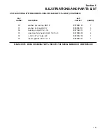
(Continued on page 121)
(I)
For maintenance on control air filter no. 02250112-032, order repair kit no. 02250112-031.
(II)
For maintenance on 3-way solenoid valve no. 02250125-657, order repair kit no. 022500125-829, and
replacement coil no. 02250125-861.
(III)
For maintenance on 2-way solenoid valve no. 02250125-679, order repair kit no. 02250125-284, and
replacement coil no. 02250125-861.
(IV)
For maintenance on regulator valve no. 045099, order repair kit no. 048409.
(V)
For maintenance on regulator valve no. 048059, order repair kit no. 048409.
PLEASE NOTE: WHEN ORDERING PARTS, INDICATE THE SERIAL NUMBER OF COMPRESSOR
Summary of Contents for TS-32S
Page 16: ...Section 2 DESCRIPTION 10 Figure 2 3A Compressor Cooling and Lubrication System Air cooled...
Page 17: ...Section 2 DESCRIPTION 11 Figure 2 3B Compressor Cooling and Lubrication System Water cooled...
Page 18: ...Section 2 DESCRIPTION 12 Figure 2 4A Compressor Discharge System Air cooled...
Page 19: ...Section 2 DESCRIPTION 13 Figure 2 4B Compressor Discharge System Water cooled...
Page 20: ...Section 2 DESCRIPTION 14 Figure 2 5A Control System START Typical...
Page 21: ...Section 2 DESCRIPTION 15 Figure 2 5B Control System MODULATION Typical...
Page 22: ...Section 2 DESCRIPTION 16 Figure 2 5C Control System UNLOAD Typical...
Page 23: ...Section 2 DESCRIPTION 17 Figure 2 5D Control System FULL LOAD Typical...
Page 27: ...Section 3 SPECIFICATIONS 21 NOTES...
Page 40: ...34 NOTES...
Page 48: ...42 NOTES...
Page 60: ...54 NOTES...
Page 63: ...57 NOTES...
Page 72: ...Section 8 ILLUSTRATIONS AND PARTS LIST 66 8 5 AIR INLET SYSTEM 02250135 499R01...
Page 114: ...Section 8 ILLUSTRATIONS AND PARTS LIST 108 02250135 534R03 8 20 SUMP AND PARTS...
Page 116: ...Section 8 ILLUSTRATIONS AND PARTS LIST 110 02250135 534R03 8 20 SUMP AND PARTS...
Page 118: ...Section 8 ILLUSTRATIONS AND PARTS LIST 112 02250134 158R00 8 21 SULLICON CONTROL...
Page 120: ...Section 8 ILLUSTRATIONS AND PARTS LIST 114 8 22 COMPRESSOR SPIRIAL VALVE ACTUATOR...
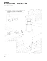
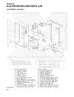
Page 124: ...Section 8 ILLUSTRATIONS AND PARTS LIST 118 02250135 643R05 8 24 PNEUMATIC CONTROLS...
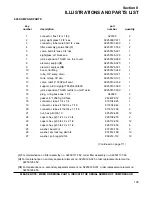
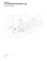
Page 126: ...Section 8 ILLUSTRATIONS AND PARTS LIST 120 02250135 643R05 8 24 PNEUMATIC CONTROLS...
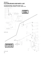
Page 128: ...Section 8 ILLUSTRATIONS AND PARTS LIST 122 02250135 643R05 8 24 PNEUMATIC CONTROLS...
Page 134: ...Section 8 ILLUSTRATIONS AND PARTS LIST 128 8 27 CONTROL BOX WYE DELTA TYPICAL 02250122 516R08...
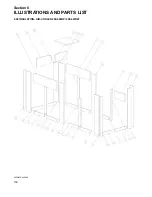
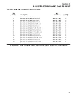
Page 140: ...Section 8 ILLUSTRATIONS AND PARTS LIST 134 02250133 674R04 8 30 ENCLOSURE AIR COOLED...
Page 142: ...Section 8 ILLUSTRATIONS AND PARTS LIST 136 02250133 674R04 8 30 ENCLOSURE AIR COOLED...
Page 144: ...Section 8 ILLUSTRATIONS AND PARTS LIST 138 02250133 675R04 8 31 ENCLOSURE WATER COOLED...
Page 146: ...Section 8 ILLUSTRATIONS AND PARTS LIST 140 02250133 675R04 8 31 ENCLOSURE WATER COOLED...
Page 148: ...Section 8 ILLUSTRATIONS AND PARTS LIST 142 8 32 DECALS...
Page 150: ...Section 8 ILLUSTRATIONS AND PARTS LIST 144 8 32 DECALS...
Page 152: ...Section 8 ILLUSTRATIONS AND PARTS LIST 146 8 32 DECALS...
Page 154: ...Section 8 ILLUSTRATIONS AND PARTS LIST 148 8 33 DECAL LOCATIONS...
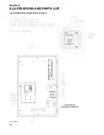
Page 156: ...Section 8 ILLUSTRATIONS AND PARTS LIST 150 8 34 DECAL LOCATIONS AIR COOLED ENCLOSURE TYPICAL...
Page 158: ...Section 8 ILLUSTRATIONS AND PARTS LIST 152 8 35 DECAL LOCATIONS WATER COOLED ENCLOSURE TYPICAL...
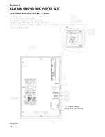
Page 160: ...Section 8 ILLUSTRATIONS AND PARTS LIST 154 8 36 DECAL LOCATIONS CONTROL BOX...
Page 162: ...Section 8 ILLUSTRATIONS AND PARTS LIST 156 8 37 DECAL LOCATIONS AFTER COOLER...
Page 171: ...NOTES...

