Section 8
ILLUSTRATIONS AND PARTS LIST
141
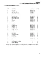
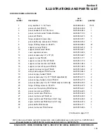
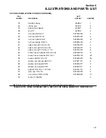
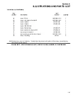
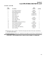
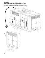
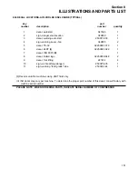
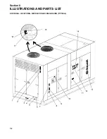
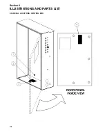
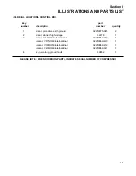
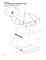
8.31 ENCLOSURE- WATER-COOLED (CONTINUED)
key
part
number
description
number
quantity
33
handle, canopy
042262
1
34
clamp, wire
043194
6
35
spacer, fan support
227267
6
36
fan, 20”
245748
2
37
nut, hex pltd 1/4-20
825104-226
2
38
nut, hex pltd 7/16-14
825207-385
6
39
nut, hex f pltd 5/16-18
825305-283
13
40
nut, hex locking 5/16-18
825505-166
2
41
capscr, hex gr5 1/4-20 x 3/4
829104-075
2
42
capscr, hex gr5 5/16-18 x 3/4
829105-075
6
43
capscr, hex gr5 7/16-14 x 3 1/2
829107-350
6
44
screw, hex ser washer 5/16-18 x 3/4
829705-075
11
45
screw, hex ser washer 5/16-18 x 1
829705-100
38
46
screw, self-drill 1/4 x 1/2
834504-050
54
47
washer, spr lock reg pltd 7/16
837807-112
6
48
washer, pl-b reg pltd 5/16
838205-071
2
49
washer, pl-b reg pltd 7/16
838207-071
6
50
eyebolt, 5/16-18 x 1 1/8” pltd
839105-112
2
51
rivet, pop 1/8 x 1/2
843102-050
4
52
nut, retainer 5/16-18 .092
861405-092
15
53
motor, 0.75hp
(II)
-
2
(II)
This part may vary by machine. Consult factory with machine serial number.
PLEASE NOTE: WHEN ORDERING PARTS, INDICATE THE SERIAL NUMBER OF COMPRESSOR
Summary of Contents for TS-32S
Page 16: ...Section 2 DESCRIPTION 10 Figure 2 3A Compressor Cooling and Lubrication System Air cooled...
Page 17: ...Section 2 DESCRIPTION 11 Figure 2 3B Compressor Cooling and Lubrication System Water cooled...
Page 18: ...Section 2 DESCRIPTION 12 Figure 2 4A Compressor Discharge System Air cooled...
Page 19: ...Section 2 DESCRIPTION 13 Figure 2 4B Compressor Discharge System Water cooled...
Page 20: ...Section 2 DESCRIPTION 14 Figure 2 5A Control System START Typical...
Page 21: ...Section 2 DESCRIPTION 15 Figure 2 5B Control System MODULATION Typical...
Page 22: ...Section 2 DESCRIPTION 16 Figure 2 5C Control System UNLOAD Typical...
Page 23: ...Section 2 DESCRIPTION 17 Figure 2 5D Control System FULL LOAD Typical...
Page 27: ...Section 3 SPECIFICATIONS 21 NOTES...
Page 40: ...34 NOTES...
Page 48: ...42 NOTES...
Page 60: ...54 NOTES...
Page 63: ...57 NOTES...
Page 72: ...Section 8 ILLUSTRATIONS AND PARTS LIST 66 8 5 AIR INLET SYSTEM 02250135 499R01...
Page 114: ...Section 8 ILLUSTRATIONS AND PARTS LIST 108 02250135 534R03 8 20 SUMP AND PARTS...
Page 116: ...Section 8 ILLUSTRATIONS AND PARTS LIST 110 02250135 534R03 8 20 SUMP AND PARTS...
Page 118: ...Section 8 ILLUSTRATIONS AND PARTS LIST 112 02250134 158R00 8 21 SULLICON CONTROL...
Page 120: ...Section 8 ILLUSTRATIONS AND PARTS LIST 114 8 22 COMPRESSOR SPIRIAL VALVE ACTUATOR...
Page 124: ...Section 8 ILLUSTRATIONS AND PARTS LIST 118 02250135 643R05 8 24 PNEUMATIC CONTROLS...
Page 126: ...Section 8 ILLUSTRATIONS AND PARTS LIST 120 02250135 643R05 8 24 PNEUMATIC CONTROLS...
Page 128: ...Section 8 ILLUSTRATIONS AND PARTS LIST 122 02250135 643R05 8 24 PNEUMATIC CONTROLS...
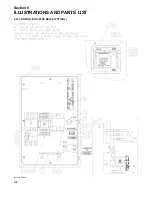
Page 134: ...Section 8 ILLUSTRATIONS AND PARTS LIST 128 8 27 CONTROL BOX WYE DELTA TYPICAL 02250122 516R08...
Page 140: ...Section 8 ILLUSTRATIONS AND PARTS LIST 134 02250133 674R04 8 30 ENCLOSURE AIR COOLED...
Page 142: ...Section 8 ILLUSTRATIONS AND PARTS LIST 136 02250133 674R04 8 30 ENCLOSURE AIR COOLED...
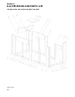
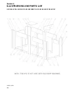
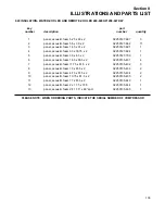
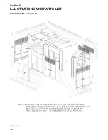
Page 144: ...Section 8 ILLUSTRATIONS AND PARTS LIST 138 02250133 675R04 8 31 ENCLOSURE WATER COOLED...
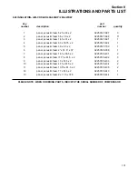
Page 146: ...Section 8 ILLUSTRATIONS AND PARTS LIST 140 02250133 675R04 8 31 ENCLOSURE WATER COOLED...
Page 148: ...Section 8 ILLUSTRATIONS AND PARTS LIST 142 8 32 DECALS...
Page 150: ...Section 8 ILLUSTRATIONS AND PARTS LIST 144 8 32 DECALS...
Page 152: ...Section 8 ILLUSTRATIONS AND PARTS LIST 146 8 32 DECALS...
Page 154: ...Section 8 ILLUSTRATIONS AND PARTS LIST 148 8 33 DECAL LOCATIONS...
Page 156: ...Section 8 ILLUSTRATIONS AND PARTS LIST 150 8 34 DECAL LOCATIONS AIR COOLED ENCLOSURE TYPICAL...
Page 158: ...Section 8 ILLUSTRATIONS AND PARTS LIST 152 8 35 DECAL LOCATIONS WATER COOLED ENCLOSURE TYPICAL...
Page 160: ...Section 8 ILLUSTRATIONS AND PARTS LIST 154 8 36 DECAL LOCATIONS CONTROL BOX...
Page 162: ...Section 8 ILLUSTRATIONS AND PARTS LIST 156 8 37 DECAL LOCATIONS AFTER COOLER...
Page 171: ...NOTES...


