Section 2
DESCRIPTION
18
to return to the full load (maximum) position.
AUTOMATIC OPERATION
For applications with varied periods of time when
there are no air requirements, Supervisor’s Auto
mode allows the compressor to shut down (time
delayed) when no compressed air requirement is
present and restart as compressed air is needed.
LOAD/ NO LOAD OPERATION
If applications call for load/no load operation, mod-
ulation can be disabled in the Supervisor
Controller
TM
in the “Control Parameters” menu. If
modulation is disabled, the unload pressure must
be reset to the rated load pressure of the machine.
For example, an L model rated for 100 psig full load
operation and 110 psig unload must have the
unload pressure reset to 100 psig. This ensures
that the motor will not run in an overload condition.
2.7 AIR INLET SYSTEM, FUNCTIONAL DESCRIP-
TION
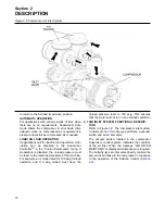
. The compressor inlet system
consists of one or two dry-type air filters, a vacuum
switch and an air inlet valve.
The vacuum switch, located in the compressor
Supervisor control system, indicates the condition
of the air filter. When the message “AIR FILTER
MAINT RQD” is displayed,maintenance is required.
The butterfly-type air inlet valve directly controls the
amount of air intake to the compressor in response
to the operation of the Sullicon Control (
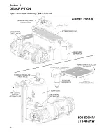
Figure 2-6 Compressor Air Inlet System
Summary of Contents for TS-32S
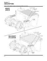
Page 16: ...Section 2 DESCRIPTION 10 Figure 2 3A Compressor Cooling and Lubrication System Air cooled...
Page 17: ...Section 2 DESCRIPTION 11 Figure 2 3B Compressor Cooling and Lubrication System Water cooled...
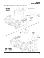
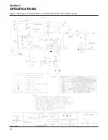
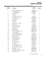
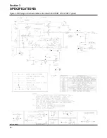
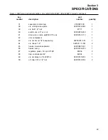
Page 18: ...Section 2 DESCRIPTION 12 Figure 2 4A Compressor Discharge System Air cooled...
Page 19: ...Section 2 DESCRIPTION 13 Figure 2 4B Compressor Discharge System Water cooled...
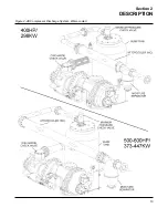
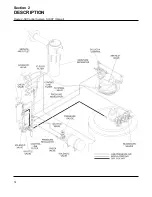
Page 20: ...Section 2 DESCRIPTION 14 Figure 2 5A Control System START Typical...
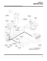
Page 21: ...Section 2 DESCRIPTION 15 Figure 2 5B Control System MODULATION Typical...
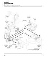
Page 22: ...Section 2 DESCRIPTION 16 Figure 2 5C Control System UNLOAD Typical...
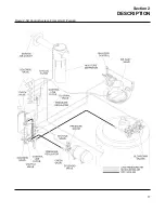
Page 23: ...Section 2 DESCRIPTION 17 Figure 2 5D Control System FULL LOAD Typical...
Page 27: ...Section 3 SPECIFICATIONS 21 NOTES...
Page 40: ...34 NOTES...
Page 48: ...42 NOTES...
Page 60: ...54 NOTES...
Page 63: ...57 NOTES...
Page 72: ...Section 8 ILLUSTRATIONS AND PARTS LIST 66 8 5 AIR INLET SYSTEM 02250135 499R01...
Page 114: ...Section 8 ILLUSTRATIONS AND PARTS LIST 108 02250135 534R03 8 20 SUMP AND PARTS...
Page 116: ...Section 8 ILLUSTRATIONS AND PARTS LIST 110 02250135 534R03 8 20 SUMP AND PARTS...
Page 118: ...Section 8 ILLUSTRATIONS AND PARTS LIST 112 02250134 158R00 8 21 SULLICON CONTROL...
Page 120: ...Section 8 ILLUSTRATIONS AND PARTS LIST 114 8 22 COMPRESSOR SPIRIAL VALVE ACTUATOR...
Page 124: ...Section 8 ILLUSTRATIONS AND PARTS LIST 118 02250135 643R05 8 24 PNEUMATIC CONTROLS...
Page 126: ...Section 8 ILLUSTRATIONS AND PARTS LIST 120 02250135 643R05 8 24 PNEUMATIC CONTROLS...
Page 128: ...Section 8 ILLUSTRATIONS AND PARTS LIST 122 02250135 643R05 8 24 PNEUMATIC CONTROLS...
Page 134: ...Section 8 ILLUSTRATIONS AND PARTS LIST 128 8 27 CONTROL BOX WYE DELTA TYPICAL 02250122 516R08...
Page 140: ...Section 8 ILLUSTRATIONS AND PARTS LIST 134 02250133 674R04 8 30 ENCLOSURE AIR COOLED...
Page 142: ...Section 8 ILLUSTRATIONS AND PARTS LIST 136 02250133 674R04 8 30 ENCLOSURE AIR COOLED...
Page 144: ...Section 8 ILLUSTRATIONS AND PARTS LIST 138 02250133 675R04 8 31 ENCLOSURE WATER COOLED...
Page 146: ...Section 8 ILLUSTRATIONS AND PARTS LIST 140 02250133 675R04 8 31 ENCLOSURE WATER COOLED...
Page 148: ...Section 8 ILLUSTRATIONS AND PARTS LIST 142 8 32 DECALS...
Page 150: ...Section 8 ILLUSTRATIONS AND PARTS LIST 144 8 32 DECALS...
Page 152: ...Section 8 ILLUSTRATIONS AND PARTS LIST 146 8 32 DECALS...
Page 154: ...Section 8 ILLUSTRATIONS AND PARTS LIST 148 8 33 DECAL LOCATIONS...
Page 156: ...Section 8 ILLUSTRATIONS AND PARTS LIST 150 8 34 DECAL LOCATIONS AIR COOLED ENCLOSURE TYPICAL...
Page 158: ...Section 8 ILLUSTRATIONS AND PARTS LIST 152 8 35 DECAL LOCATIONS WATER COOLED ENCLOSURE TYPICAL...
Page 160: ...Section 8 ILLUSTRATIONS AND PARTS LIST 154 8 36 DECAL LOCATIONS CONTROL BOX...
Page 162: ...Section 8 ILLUSTRATIONS AND PARTS LIST 156 8 37 DECAL LOCATIONS AFTER COOLER...
Page 171: ...NOTES...

