Section 3
SPECIFICATIONS
27
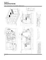
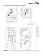
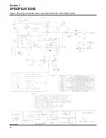
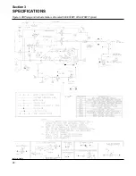
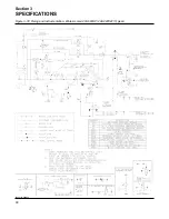
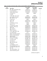
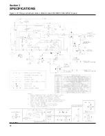
Figure 3-3B Piping and Instrumentation- Air-cooled 500-600HP/ 373-447KW (Typical)
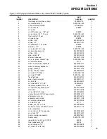
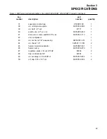
key
part
number
description
number
quantity
1
filter, assy air inlet (heavy duty)
250006-718
2
2
vlv , inlet butterfly 8"
02250126 -220
1
3
control, Sullicon LS25S
011682-003
1
4
vlv, shuttle 1/4"
408893
2
5
vlv, spiral
-
1
6
vlv, diff. press. reg. 1/4.” npt
406929
1
7
vlv, sol 3wno 1 /4" 115v ac
02250125 -657
1
8
filter, control 1/4" npt
02250112-032
2
9
vlv, press. reg.
408275
1
10
orifice, .032"
02250125-774
1
11
orifice, .03"
02250101-191
1
12
vlv, blowdown 1" nc 2-way
409783
2
13
strainer, y 1/2"
406480
1
14
vlv, solenoid 1/4" 2-way
02250125-679
2
15
pressure transducer n4
02250078-933
4
16
orifice, .094
02250125-776
1
17
glass, sight 1/4"
02250126-129
2
18
strainer, in line sae
02250117-782
2
19
vlv, min. press. check 4 " npt
02250050 -630
1
20
vlv, moisture bleed
41111
1
21
element, secondary separator
02250126-331
1
22
element, primary separator
02250126-325
1
23
gauge, pressure
02250117-009
2
24
probe, 100 ohm rtd 20'
02250044-985
4
25
vlv, relief 1 /2" 150 psi
02250092 -138
1
26
vlv, relief 2" 160#
02250132-162
1
27
tank, fluid sep.
02250129-137
1
28
glass, fluid level sight
02250097-611
2
29
vlv, ball 3/4"
02250125-221
1
30
vlv, relief 60# 2" x 2 -1/2"
250029-330
2
31
tank, accumulator 415 cu. in.
242221
1
32
vlv, thermal assy w/sae ports
02250120-955
1
33
filter, fluid
02250121-638
1
34
vlv, sol EES 1/4" 4-way
02250056-983
1
35
cooler, fluid w/1-7/8"-12 sae oil ports
02250127-107
1
36
aftercooler, air to air
02250127-710
1
(Continued on page 29)
Summary of Contents for TS-32S
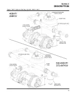
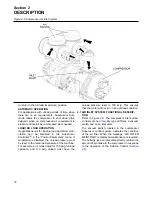
Page 16: ...Section 2 DESCRIPTION 10 Figure 2 3A Compressor Cooling and Lubrication System Air cooled...
Page 17: ...Section 2 DESCRIPTION 11 Figure 2 3B Compressor Cooling and Lubrication System Water cooled...
Page 18: ...Section 2 DESCRIPTION 12 Figure 2 4A Compressor Discharge System Air cooled...
Page 19: ...Section 2 DESCRIPTION 13 Figure 2 4B Compressor Discharge System Water cooled...
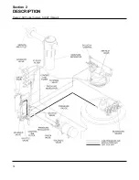
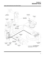
Page 20: ...Section 2 DESCRIPTION 14 Figure 2 5A Control System START Typical...
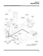
Page 21: ...Section 2 DESCRIPTION 15 Figure 2 5B Control System MODULATION Typical...
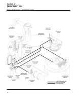
Page 22: ...Section 2 DESCRIPTION 16 Figure 2 5C Control System UNLOAD Typical...
Page 23: ...Section 2 DESCRIPTION 17 Figure 2 5D Control System FULL LOAD Typical...
Page 27: ...Section 3 SPECIFICATIONS 21 NOTES...
Page 40: ...34 NOTES...
Page 48: ...42 NOTES...
Page 60: ...54 NOTES...
Page 63: ...57 NOTES...
Page 72: ...Section 8 ILLUSTRATIONS AND PARTS LIST 66 8 5 AIR INLET SYSTEM 02250135 499R01...
Page 114: ...Section 8 ILLUSTRATIONS AND PARTS LIST 108 02250135 534R03 8 20 SUMP AND PARTS...
Page 116: ...Section 8 ILLUSTRATIONS AND PARTS LIST 110 02250135 534R03 8 20 SUMP AND PARTS...
Page 118: ...Section 8 ILLUSTRATIONS AND PARTS LIST 112 02250134 158R00 8 21 SULLICON CONTROL...
Page 120: ...Section 8 ILLUSTRATIONS AND PARTS LIST 114 8 22 COMPRESSOR SPIRIAL VALVE ACTUATOR...
Page 124: ...Section 8 ILLUSTRATIONS AND PARTS LIST 118 02250135 643R05 8 24 PNEUMATIC CONTROLS...
Page 126: ...Section 8 ILLUSTRATIONS AND PARTS LIST 120 02250135 643R05 8 24 PNEUMATIC CONTROLS...
Page 128: ...Section 8 ILLUSTRATIONS AND PARTS LIST 122 02250135 643R05 8 24 PNEUMATIC CONTROLS...
Page 134: ...Section 8 ILLUSTRATIONS AND PARTS LIST 128 8 27 CONTROL BOX WYE DELTA TYPICAL 02250122 516R08...
Page 140: ...Section 8 ILLUSTRATIONS AND PARTS LIST 134 02250133 674R04 8 30 ENCLOSURE AIR COOLED...
Page 142: ...Section 8 ILLUSTRATIONS AND PARTS LIST 136 02250133 674R04 8 30 ENCLOSURE AIR COOLED...
Page 144: ...Section 8 ILLUSTRATIONS AND PARTS LIST 138 02250133 675R04 8 31 ENCLOSURE WATER COOLED...
Page 146: ...Section 8 ILLUSTRATIONS AND PARTS LIST 140 02250133 675R04 8 31 ENCLOSURE WATER COOLED...
Page 148: ...Section 8 ILLUSTRATIONS AND PARTS LIST 142 8 32 DECALS...
Page 150: ...Section 8 ILLUSTRATIONS AND PARTS LIST 144 8 32 DECALS...
Page 152: ...Section 8 ILLUSTRATIONS AND PARTS LIST 146 8 32 DECALS...
Page 154: ...Section 8 ILLUSTRATIONS AND PARTS LIST 148 8 33 DECAL LOCATIONS...
Page 156: ...Section 8 ILLUSTRATIONS AND PARTS LIST 150 8 34 DECAL LOCATIONS AIR COOLED ENCLOSURE TYPICAL...
Page 158: ...Section 8 ILLUSTRATIONS AND PARTS LIST 152 8 35 DECAL LOCATIONS WATER COOLED ENCLOSURE TYPICAL...
Page 160: ...Section 8 ILLUSTRATIONS AND PARTS LIST 154 8 36 DECAL LOCATIONS CONTROL BOX...
Page 162: ...Section 8 ILLUSTRATIONS AND PARTS LIST 156 8 37 DECAL LOCATIONS AFTER COOLER...
Page 171: ...NOTES...

