Section 7
MAINTENANCE
44
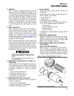
tions below. For element replacement order kit
number 02250139-996.
1. Drain the fluid from the canister by removing the
bottom drain plug
2. Loosen the spin-on canister using a wrench on
the bottom canister hex.
3. Pull the canister away from the filter head. The
filter element will be attached to the head.
4. Separate the element from the head.
5. Remove the canister seals.
6. Thoroughly clean the filter head and canister in
solvent.
7. Lubricate the new seals with the same type of
fluid used in the compressor and position each
seal in its appropriate place.
8. Slide the element into the canister.
9. Thread the canister and element back on the fil-
ter head.
AIR FILTER MAINTENANCE
. Air filter maintenance should
be performed when the air filter maintenance mes-
sage is displayed. The air filter is equipped with a
primary element and a secondary element. As pre-
viously stated, the Supervisor will alert you as to
when the primary element maintenance is neces-
sary. When removing the primary element, always
check the secondary element for visible dirt, grease
or damage. The secondary element must be
changed after every sixth primary element change.
DO NOT
clean the secondary element.
ELEMENT REMOVAL
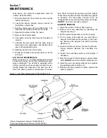
1. Clean the exterior of the air filter housing.
2. Remove the cover assembly by loosening the
wingnut securing it.
3. Pull the element assembly out of the housing.
4. On the inside of the element, you will notice a
wingnut which fastens the element to the hous-
ing. Remove the wingnut and pull the primary
element out.
5. Loosen and remove the hex nut securing the sec-
ondary element. Remove the secondary ele-
ment.
6. Inspect the secondary element and replace if
necessary.
7. Clean the interior of the housing by using a damp
cloth.
DO NOT
blow dirt out with compressor air.
8. Install the new secondary element and replace
the sealing washer and hex nut.
9. With the secondary element in place, replace the
primary element.
Figure 7-2 Air Filter Replacement (P/N 250006-718)
*Primary Replacement Element P/N 250007-838
**Secondary Replacement Element P/N 250007-839
Summary of Contents for TS-32S
Page 16: ...Section 2 DESCRIPTION 10 Figure 2 3A Compressor Cooling and Lubrication System Air cooled...
Page 17: ...Section 2 DESCRIPTION 11 Figure 2 3B Compressor Cooling and Lubrication System Water cooled...
Page 18: ...Section 2 DESCRIPTION 12 Figure 2 4A Compressor Discharge System Air cooled...
Page 19: ...Section 2 DESCRIPTION 13 Figure 2 4B Compressor Discharge System Water cooled...
Page 20: ...Section 2 DESCRIPTION 14 Figure 2 5A Control System START Typical...
Page 21: ...Section 2 DESCRIPTION 15 Figure 2 5B Control System MODULATION Typical...
Page 22: ...Section 2 DESCRIPTION 16 Figure 2 5C Control System UNLOAD Typical...
Page 23: ...Section 2 DESCRIPTION 17 Figure 2 5D Control System FULL LOAD Typical...
Page 27: ...Section 3 SPECIFICATIONS 21 NOTES...
Page 40: ...34 NOTES...
Page 48: ...42 NOTES...
Page 60: ...54 NOTES...
Page 63: ...57 NOTES...
Page 72: ...Section 8 ILLUSTRATIONS AND PARTS LIST 66 8 5 AIR INLET SYSTEM 02250135 499R01...
Page 114: ...Section 8 ILLUSTRATIONS AND PARTS LIST 108 02250135 534R03 8 20 SUMP AND PARTS...
Page 116: ...Section 8 ILLUSTRATIONS AND PARTS LIST 110 02250135 534R03 8 20 SUMP AND PARTS...
Page 118: ...Section 8 ILLUSTRATIONS AND PARTS LIST 112 02250134 158R00 8 21 SULLICON CONTROL...
Page 120: ...Section 8 ILLUSTRATIONS AND PARTS LIST 114 8 22 COMPRESSOR SPIRIAL VALVE ACTUATOR...
Page 124: ...Section 8 ILLUSTRATIONS AND PARTS LIST 118 02250135 643R05 8 24 PNEUMATIC CONTROLS...
Page 126: ...Section 8 ILLUSTRATIONS AND PARTS LIST 120 02250135 643R05 8 24 PNEUMATIC CONTROLS...
Page 128: ...Section 8 ILLUSTRATIONS AND PARTS LIST 122 02250135 643R05 8 24 PNEUMATIC CONTROLS...
Page 134: ...Section 8 ILLUSTRATIONS AND PARTS LIST 128 8 27 CONTROL BOX WYE DELTA TYPICAL 02250122 516R08...
Page 140: ...Section 8 ILLUSTRATIONS AND PARTS LIST 134 02250133 674R04 8 30 ENCLOSURE AIR COOLED...
Page 142: ...Section 8 ILLUSTRATIONS AND PARTS LIST 136 02250133 674R04 8 30 ENCLOSURE AIR COOLED...
Page 144: ...Section 8 ILLUSTRATIONS AND PARTS LIST 138 02250133 675R04 8 31 ENCLOSURE WATER COOLED...
Page 146: ...Section 8 ILLUSTRATIONS AND PARTS LIST 140 02250133 675R04 8 31 ENCLOSURE WATER COOLED...
Page 148: ...Section 8 ILLUSTRATIONS AND PARTS LIST 142 8 32 DECALS...
Page 150: ...Section 8 ILLUSTRATIONS AND PARTS LIST 144 8 32 DECALS...
Page 152: ...Section 8 ILLUSTRATIONS AND PARTS LIST 146 8 32 DECALS...
Page 154: ...Section 8 ILLUSTRATIONS AND PARTS LIST 148 8 33 DECAL LOCATIONS...
Page 156: ...Section 8 ILLUSTRATIONS AND PARTS LIST 150 8 34 DECAL LOCATIONS AIR COOLED ENCLOSURE TYPICAL...
Page 158: ...Section 8 ILLUSTRATIONS AND PARTS LIST 152 8 35 DECAL LOCATIONS WATER COOLED ENCLOSURE TYPICAL...
Page 160: ...Section 8 ILLUSTRATIONS AND PARTS LIST 154 8 36 DECAL LOCATIONS CONTROL BOX...
Page 162: ...Section 8 ILLUSTRATIONS AND PARTS LIST 156 8 37 DECAL LOCATIONS AFTER COOLER...
Page 171: ...NOTES...

