Section 7
MAINTENANCE
46
(271 Nm).
11. Reconnect all piping making sure return line
tubes extend to the bottom or 1/4” (6mm) above
the bottom of the separator element. This will
assure proper fluid return flow to the compres-
sor.
12. Check the return line strainers before restarting
the compressor (order replacement kit no.
02250117-782).
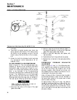
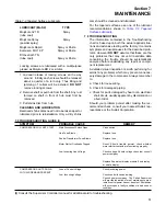
OIL RETURN/SIGHT GLASS MAINTENANCE
. The oil return/sight glass sub-
assembly is attached to the separator tank lid.Oil
return/sight glass maintenance should be per-
formed on a routine basis parallel to that of the fluid
filter, or as indicated in the Troubleshooting
Sections (both Supervisor and Maintenance) of this
manual. The maintenance on an oil return/sight
glass is mainly concerned with the condition of the
filter assembly. Order filter assembly no. 02250117-
782, and use the following instructions as a guide.
Always performing maintenance on both oil
return/sight glasses at the same time.
1. Disconnect the tubes at the tops of the sight
glass assemblies.
2. Unscrew male connector (for left-side glass), or
the straight thread tube connector (for right-side
glass) from sight glass/orifice blocks.
3. Remove used filter assembly, and replace with
new assembly.
4. Coat/lubricate the O-rings will silicone grease.
5. Reattach the connectors to the sight glass/orifice
blocks.
DIFFERENTIAL
PRESSURE REGULATOR
ADJUSTMENT
. The differential pres-
sure regulators are adjusted by loosening the jam
nut on the end of the cone shaped cover of the
pressure regulator. When the jam nut is loose, turn
the adjusting screw clockwise to increase or coun-
terclockwise to decrease the setting.
Above 100 psig (6.9 bar), the spiral valve regulator
should allow pressure to flow into the chamber of
the spiral valve actuator. The spiral valve should
start to rotate at this time.
At approximately 108 psig (7.5 bar), the Sullicon
regulator should allow pressure to flow into the con-
trol chamber of the Sullicon Control. The Sullicon
Control level should start to move at this time. Cycle
the Control System several times and recheck all
pressure settings.
Figure 7-4 Oil Return/Sight Glass
*Replacement Filter Assembly P/N 02250117-782
Summary of Contents for TS-32S
Page 16: ...Section 2 DESCRIPTION 10 Figure 2 3A Compressor Cooling and Lubrication System Air cooled...
Page 17: ...Section 2 DESCRIPTION 11 Figure 2 3B Compressor Cooling and Lubrication System Water cooled...
Page 18: ...Section 2 DESCRIPTION 12 Figure 2 4A Compressor Discharge System Air cooled...
Page 19: ...Section 2 DESCRIPTION 13 Figure 2 4B Compressor Discharge System Water cooled...
Page 20: ...Section 2 DESCRIPTION 14 Figure 2 5A Control System START Typical...
Page 21: ...Section 2 DESCRIPTION 15 Figure 2 5B Control System MODULATION Typical...
Page 22: ...Section 2 DESCRIPTION 16 Figure 2 5C Control System UNLOAD Typical...
Page 23: ...Section 2 DESCRIPTION 17 Figure 2 5D Control System FULL LOAD Typical...
Page 27: ...Section 3 SPECIFICATIONS 21 NOTES...
Page 40: ...34 NOTES...
Page 48: ...42 NOTES...
Page 60: ...54 NOTES...
Page 63: ...57 NOTES...
Page 72: ...Section 8 ILLUSTRATIONS AND PARTS LIST 66 8 5 AIR INLET SYSTEM 02250135 499R01...
Page 114: ...Section 8 ILLUSTRATIONS AND PARTS LIST 108 02250135 534R03 8 20 SUMP AND PARTS...
Page 116: ...Section 8 ILLUSTRATIONS AND PARTS LIST 110 02250135 534R03 8 20 SUMP AND PARTS...
Page 118: ...Section 8 ILLUSTRATIONS AND PARTS LIST 112 02250134 158R00 8 21 SULLICON CONTROL...
Page 120: ...Section 8 ILLUSTRATIONS AND PARTS LIST 114 8 22 COMPRESSOR SPIRIAL VALVE ACTUATOR...
Page 124: ...Section 8 ILLUSTRATIONS AND PARTS LIST 118 02250135 643R05 8 24 PNEUMATIC CONTROLS...
Page 126: ...Section 8 ILLUSTRATIONS AND PARTS LIST 120 02250135 643R05 8 24 PNEUMATIC CONTROLS...
Page 128: ...Section 8 ILLUSTRATIONS AND PARTS LIST 122 02250135 643R05 8 24 PNEUMATIC CONTROLS...
Page 134: ...Section 8 ILLUSTRATIONS AND PARTS LIST 128 8 27 CONTROL BOX WYE DELTA TYPICAL 02250122 516R08...
Page 140: ...Section 8 ILLUSTRATIONS AND PARTS LIST 134 02250133 674R04 8 30 ENCLOSURE AIR COOLED...
Page 142: ...Section 8 ILLUSTRATIONS AND PARTS LIST 136 02250133 674R04 8 30 ENCLOSURE AIR COOLED...
Page 144: ...Section 8 ILLUSTRATIONS AND PARTS LIST 138 02250133 675R04 8 31 ENCLOSURE WATER COOLED...
Page 146: ...Section 8 ILLUSTRATIONS AND PARTS LIST 140 02250133 675R04 8 31 ENCLOSURE WATER COOLED...
Page 148: ...Section 8 ILLUSTRATIONS AND PARTS LIST 142 8 32 DECALS...
Page 150: ...Section 8 ILLUSTRATIONS AND PARTS LIST 144 8 32 DECALS...
Page 152: ...Section 8 ILLUSTRATIONS AND PARTS LIST 146 8 32 DECALS...
Page 154: ...Section 8 ILLUSTRATIONS AND PARTS LIST 148 8 33 DECAL LOCATIONS...
Page 156: ...Section 8 ILLUSTRATIONS AND PARTS LIST 150 8 34 DECAL LOCATIONS AIR COOLED ENCLOSURE TYPICAL...
Page 158: ...Section 8 ILLUSTRATIONS AND PARTS LIST 152 8 35 DECAL LOCATIONS WATER COOLED ENCLOSURE TYPICAL...
Page 160: ...Section 8 ILLUSTRATIONS AND PARTS LIST 154 8 36 DECAL LOCATIONS CONTROL BOX...
Page 162: ...Section 8 ILLUSTRATIONS AND PARTS LIST 156 8 37 DECAL LOCATIONS AFTER COOLER...
Page 171: ...NOTES...

