Section 7
MAINTENANCE
47
COMPRESSOR DRIVE COUPLING
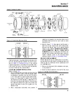
The performance and life of couplings depend
largely upon how you install and maintain them.
Before installing couplings, make certain that
foundations of equipment to be connected meet
requirements of Section
must be aligned after installation and prior to ini-
tial start-up of the compressor.
The use of stainless steel shims under the motor
feet is recommended. Measuring misalignment and
positioning equipment within alignment tolerances
is simplified with an alignment computer. These cal-
culations can also be done graphically or mathe-
matically.
ANNUAL MAINTENANCE- DRIVE COUPLING
Disconnect all power at source before attempting
maintenance or adjustments.
1. Check alignment per Step 3. If operation limits
are exceeded,
realign coupling to installation limits.
2. Check outer blades of discpacks near bushings
for fatigue cracks. Discpacks can be checked
while coupling is in operation by using a strobe
light. Replace cracked discpacks and recheck
alignment. A slight bowing or “S”-like distortion is
normal.
3. Check tightening torques of all drive bolts.
Standard mechanics tools, torque wrenches, a
straight edge and feeler gauges or dial indicators
and brackets and micrometers are required to
install couplings. A 17mm end wrench is required
for shrink disc locking screws. For best results use
a dial indicator to check final alignment and make
certain bolts are tightened to the required elonga-
tion or torque listed in
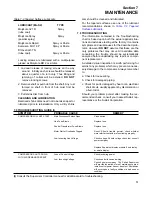
The drive bolts have been factory tightened to the
required elongation indicated in
, and should not be disturbed.
STEP 1- HUB INSTALLATION
MOTOR HUB INSTALLATION FOR MOTOR HUB
MOUNTING
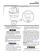
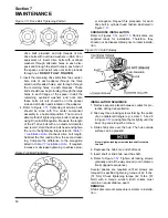
Coupling is furnished for an interference fit with a
set screw. Heat hub to 275ºF (135ºC) using an
oven, torch, induction heater or an oil bath.
To prevent damage DO NOT heat hubs beyond a
maximum temperature of 400ºF (205ºC).
When an oxy-acetylene or blow torch is used, use
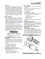
Figure 7-5 Pressure Regulator Adjustments
Summary of Contents for TS-32S
Page 16: ...Section 2 DESCRIPTION 10 Figure 2 3A Compressor Cooling and Lubrication System Air cooled...
Page 17: ...Section 2 DESCRIPTION 11 Figure 2 3B Compressor Cooling and Lubrication System Water cooled...
Page 18: ...Section 2 DESCRIPTION 12 Figure 2 4A Compressor Discharge System Air cooled...
Page 19: ...Section 2 DESCRIPTION 13 Figure 2 4B Compressor Discharge System Water cooled...
Page 20: ...Section 2 DESCRIPTION 14 Figure 2 5A Control System START Typical...
Page 21: ...Section 2 DESCRIPTION 15 Figure 2 5B Control System MODULATION Typical...
Page 22: ...Section 2 DESCRIPTION 16 Figure 2 5C Control System UNLOAD Typical...
Page 23: ...Section 2 DESCRIPTION 17 Figure 2 5D Control System FULL LOAD Typical...
Page 27: ...Section 3 SPECIFICATIONS 21 NOTES...
Page 40: ...34 NOTES...
Page 48: ...42 NOTES...
Page 60: ...54 NOTES...
Page 63: ...57 NOTES...
Page 72: ...Section 8 ILLUSTRATIONS AND PARTS LIST 66 8 5 AIR INLET SYSTEM 02250135 499R01...
Page 114: ...Section 8 ILLUSTRATIONS AND PARTS LIST 108 02250135 534R03 8 20 SUMP AND PARTS...
Page 116: ...Section 8 ILLUSTRATIONS AND PARTS LIST 110 02250135 534R03 8 20 SUMP AND PARTS...
Page 118: ...Section 8 ILLUSTRATIONS AND PARTS LIST 112 02250134 158R00 8 21 SULLICON CONTROL...
Page 120: ...Section 8 ILLUSTRATIONS AND PARTS LIST 114 8 22 COMPRESSOR SPIRIAL VALVE ACTUATOR...
Page 124: ...Section 8 ILLUSTRATIONS AND PARTS LIST 118 02250135 643R05 8 24 PNEUMATIC CONTROLS...
Page 126: ...Section 8 ILLUSTRATIONS AND PARTS LIST 120 02250135 643R05 8 24 PNEUMATIC CONTROLS...
Page 128: ...Section 8 ILLUSTRATIONS AND PARTS LIST 122 02250135 643R05 8 24 PNEUMATIC CONTROLS...
Page 134: ...Section 8 ILLUSTRATIONS AND PARTS LIST 128 8 27 CONTROL BOX WYE DELTA TYPICAL 02250122 516R08...
Page 140: ...Section 8 ILLUSTRATIONS AND PARTS LIST 134 02250133 674R04 8 30 ENCLOSURE AIR COOLED...
Page 142: ...Section 8 ILLUSTRATIONS AND PARTS LIST 136 02250133 674R04 8 30 ENCLOSURE AIR COOLED...
Page 144: ...Section 8 ILLUSTRATIONS AND PARTS LIST 138 02250133 675R04 8 31 ENCLOSURE WATER COOLED...
Page 146: ...Section 8 ILLUSTRATIONS AND PARTS LIST 140 02250133 675R04 8 31 ENCLOSURE WATER COOLED...
Page 148: ...Section 8 ILLUSTRATIONS AND PARTS LIST 142 8 32 DECALS...
Page 150: ...Section 8 ILLUSTRATIONS AND PARTS LIST 144 8 32 DECALS...
Page 152: ...Section 8 ILLUSTRATIONS AND PARTS LIST 146 8 32 DECALS...
Page 154: ...Section 8 ILLUSTRATIONS AND PARTS LIST 148 8 33 DECAL LOCATIONS...
Page 156: ...Section 8 ILLUSTRATIONS AND PARTS LIST 150 8 34 DECAL LOCATIONS AIR COOLED ENCLOSURE TYPICAL...
Page 158: ...Section 8 ILLUSTRATIONS AND PARTS LIST 152 8 35 DECAL LOCATIONS WATER COOLED ENCLOSURE TYPICAL...
Page 160: ...Section 8 ILLUSTRATIONS AND PARTS LIST 154 8 36 DECAL LOCATIONS CONTROL BOX...
Page 162: ...Section 8 ILLUSTRATIONS AND PARTS LIST 156 8 37 DECAL LOCATIONS AFTER COOLER...
Page 171: ...NOTES...


