Section 7
MAINTENANCE
48
an excess acetylene mixture. Mark hubs near the
center of their length in several places on hub body
with a temperature sensitive crayon, 275ºF (135ºC)
melt temperature. Direct flame towards hub bore
using constant motion to avoid overheating an area.
If an oil bath is used, the oil must have a flash
point of 350ºF (177ºC) or higher. Do not rest hubs
on the bottom of the container. Do not use an open
flame in a combustible atmosphere or near com-
bustible materials.
Heat hubs as instructed above. Mount hubs as
quickly as possible with hub flange face flush with
shaft end. Allow hubs to cool before proceeding.
Insert set screws (if required) and tighten.
COMPRESSOR HUB INSTALLATION
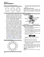
Refer to shrink disc installation sequence before
mounting special compressor hub assembly. Slide
compressor hub and shrink disc assembly onto
compressor hub. Shaft should be recessed 3/8”
from face of hub. Gradually tighten all shrink disc
locking screws to 42 ft. lbs. torque per step no. 6,
(under INSTALLATION SEQUENCE), and Figure
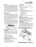
STEP 2 OFFSET ALIGNMENT
- Position equip-
ment for coupling gap approximately 7” (178mm).
Align the shafts so that a straight edge will rest
squarely (or within the offset limits specified in
) on both flanges and at a point
90º away. Vertical offset alignment is adjusted by
the addition or removal of motor mounting shims.
Loosen motor mounting bolts and slide the motor
sideways to correct the horizontal offset.
STEP 3 COUPLING GAP AND ANGULAR ALIGN-
MENT
- Align shafts within the angular limits and to
the coupling gap specified in
. To determine angular misalignment in inches,
measure the maximum space between flanges and
the minimum space 180º away, then subtract. To
adjust the motor mounting bolts and adjust the
motor position until the angular alignment is within
tolerance.
DO NOT upset the offset alignment or hub gap
when adjusting motor position.
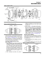
Figure 7-7 Parallel/ Angular Offset Alignment
Figure 7-6 Drive Coupling Alignment
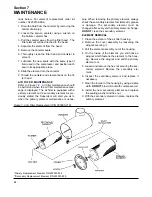
Table 7-1 Installation Data
Max. Operating Misalignment
Adapter Bolt
Coupling
Drive Bolt
Drive Bolt
Tightening
Coupling
Parallel
Capscrew
Tightening
Elongation
Torque, Oiled
Gap
Offset
Angular
Torque, Oiled
Inches
ft.-lbs./ Nm
+ .030 inches
Inches
Deg.
Inches(I)
ft.-lbs./ Nm
28/ 38
7.00
T.I.R. .005
.5
.005
169/ 229
.0050-.0060
(I)
Angular misalignment in inches equals maximum A minus minimum B as shown in Figure
values in Table above.
Summary of Contents for TS-32S
Page 16: ...Section 2 DESCRIPTION 10 Figure 2 3A Compressor Cooling and Lubrication System Air cooled...
Page 17: ...Section 2 DESCRIPTION 11 Figure 2 3B Compressor Cooling and Lubrication System Water cooled...
Page 18: ...Section 2 DESCRIPTION 12 Figure 2 4A Compressor Discharge System Air cooled...
Page 19: ...Section 2 DESCRIPTION 13 Figure 2 4B Compressor Discharge System Water cooled...
Page 20: ...Section 2 DESCRIPTION 14 Figure 2 5A Control System START Typical...
Page 21: ...Section 2 DESCRIPTION 15 Figure 2 5B Control System MODULATION Typical...
Page 22: ...Section 2 DESCRIPTION 16 Figure 2 5C Control System UNLOAD Typical...
Page 23: ...Section 2 DESCRIPTION 17 Figure 2 5D Control System FULL LOAD Typical...
Page 27: ...Section 3 SPECIFICATIONS 21 NOTES...
Page 40: ...34 NOTES...
Page 48: ...42 NOTES...
Page 60: ...54 NOTES...
Page 63: ...57 NOTES...
Page 72: ...Section 8 ILLUSTRATIONS AND PARTS LIST 66 8 5 AIR INLET SYSTEM 02250135 499R01...
Page 114: ...Section 8 ILLUSTRATIONS AND PARTS LIST 108 02250135 534R03 8 20 SUMP AND PARTS...
Page 116: ...Section 8 ILLUSTRATIONS AND PARTS LIST 110 02250135 534R03 8 20 SUMP AND PARTS...
Page 118: ...Section 8 ILLUSTRATIONS AND PARTS LIST 112 02250134 158R00 8 21 SULLICON CONTROL...
Page 120: ...Section 8 ILLUSTRATIONS AND PARTS LIST 114 8 22 COMPRESSOR SPIRIAL VALVE ACTUATOR...
Page 124: ...Section 8 ILLUSTRATIONS AND PARTS LIST 118 02250135 643R05 8 24 PNEUMATIC CONTROLS...
Page 126: ...Section 8 ILLUSTRATIONS AND PARTS LIST 120 02250135 643R05 8 24 PNEUMATIC CONTROLS...
Page 128: ...Section 8 ILLUSTRATIONS AND PARTS LIST 122 02250135 643R05 8 24 PNEUMATIC CONTROLS...
Page 134: ...Section 8 ILLUSTRATIONS AND PARTS LIST 128 8 27 CONTROL BOX WYE DELTA TYPICAL 02250122 516R08...
Page 140: ...Section 8 ILLUSTRATIONS AND PARTS LIST 134 02250133 674R04 8 30 ENCLOSURE AIR COOLED...
Page 142: ...Section 8 ILLUSTRATIONS AND PARTS LIST 136 02250133 674R04 8 30 ENCLOSURE AIR COOLED...
Page 144: ...Section 8 ILLUSTRATIONS AND PARTS LIST 138 02250133 675R04 8 31 ENCLOSURE WATER COOLED...
Page 146: ...Section 8 ILLUSTRATIONS AND PARTS LIST 140 02250133 675R04 8 31 ENCLOSURE WATER COOLED...
Page 148: ...Section 8 ILLUSTRATIONS AND PARTS LIST 142 8 32 DECALS...
Page 150: ...Section 8 ILLUSTRATIONS AND PARTS LIST 144 8 32 DECALS...
Page 152: ...Section 8 ILLUSTRATIONS AND PARTS LIST 146 8 32 DECALS...
Page 154: ...Section 8 ILLUSTRATIONS AND PARTS LIST 148 8 33 DECAL LOCATIONS...
Page 156: ...Section 8 ILLUSTRATIONS AND PARTS LIST 150 8 34 DECAL LOCATIONS AIR COOLED ENCLOSURE TYPICAL...
Page 158: ...Section 8 ILLUSTRATIONS AND PARTS LIST 152 8 35 DECAL LOCATIONS WATER COOLED ENCLOSURE TYPICAL...
Page 160: ...Section 8 ILLUSTRATIONS AND PARTS LIST 154 8 36 DECAL LOCATIONS CONTROL BOX...
Page 162: ...Section 8 ILLUSTRATIONS AND PARTS LIST 156 8 37 DECAL LOCATIONS AFTER COOLER...
Page 171: ...NOTES...

