Section 7
MAINTENANCE
51
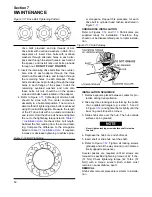
1. Gradual release of locking screws all the way
around. Initially each screw should be released
about a quarter of a turn only. Thus tilting and
jamming of collars will be avoided.
DO NOT
remove locking screws.
2. Remove shaft or pull hub from the shaft. Any rust
formed on shaft in front of hub must first be
removed.
3. Pull shrink disc from hub.
CLEANING AND LUBRICATION
Removed shrink discs need not to be taken apart or
lubricated prior to reinstallation. Only a dirty shrink
disc should be cleaned and lubricated.
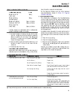
For the tapered surfaces, use one of the lubricant
recommendations shown in
7.8 TROUBLESHOOTING
The information contained in the Troubleshooting
chart is based upon both the actual applied situa-
tions and extensive testing at the factory. It contains
symptoms and usual causes for the described prob-
lems. However
DO NOT
assume that these are the
only problems that may occur. All available data
concerning the trouble should be systematically
analyzed before undertaking any repair or compo-
nent replacement.
A detailed visual inspection is worth performing for
almost any problems which may prevent unneces-
sary damage to the compressor. Always remember
to:
a. Check for loose wiring.
b. Check for damaged piping.
c. Check for parts damaged by heat or an electrical
short circuit, usually apparent by discoloration or
a burnt odor.
Should your problem persist after making the rec-
ommended check, consult your nearest Sullair rep-
resentative or the Sullair Corporation.
LUBRICANT (MoS2)
TYPE
Molykote 321 R
Spray
(lube coat)
Molykote Spray
Spray
(powder spray)
Molykote G Rapid
Spray or Paste
Aemason MO 19 P
Spray or Paste
DIO-setral 57 N
(lube coat)
Spray or Paste
Locking screws are lubricated with a multipurpose
grease as Molykote BR 2 or similar.
Table 7-2 Tapered Surface Lubricants
COMPRESSOR WILL NOT START
COMPRESSOR SHUTS DOWN
WITH AIR DEMAND PRESENT
Main Disconnect Switch Open
Line Fuse Blown
Control Transformer Fuse Blown
Motor Starter Overloads Tripped
Low Incoming Line Voltage
Loss of Control Voltage
Low Incoming Voltage
Close switch.
Replace fuse.
Replace fuse.
Reset. Should trouble persist, check whether
motor starter contacts are functioning properly.
Check voltage. Should voltage check low, consult
power company.
Replace Supervisor display module if no display
or erratic display.
Check incoming power.
Check control fuses and wiring.
Consult power company. The Sullair Supervisor
will provide indication of most maintenance prob-
lems if control power has not been lost. Shutdowns
will occur upon a faulty condition or a bad sender
condition.
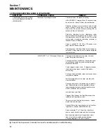
7.9 TROUBLESHOOTING GUIDE (I)
SYMPTOM
PROBABLE CAUSE
REMEDY
(I)
Consult the Supervisor Controller manual for additional aid to troubleshooting.
Summary of Contents for TS-32S
Page 16: ...Section 2 DESCRIPTION 10 Figure 2 3A Compressor Cooling and Lubrication System Air cooled...
Page 17: ...Section 2 DESCRIPTION 11 Figure 2 3B Compressor Cooling and Lubrication System Water cooled...
Page 18: ...Section 2 DESCRIPTION 12 Figure 2 4A Compressor Discharge System Air cooled...
Page 19: ...Section 2 DESCRIPTION 13 Figure 2 4B Compressor Discharge System Water cooled...
Page 20: ...Section 2 DESCRIPTION 14 Figure 2 5A Control System START Typical...
Page 21: ...Section 2 DESCRIPTION 15 Figure 2 5B Control System MODULATION Typical...
Page 22: ...Section 2 DESCRIPTION 16 Figure 2 5C Control System UNLOAD Typical...
Page 23: ...Section 2 DESCRIPTION 17 Figure 2 5D Control System FULL LOAD Typical...
Page 27: ...Section 3 SPECIFICATIONS 21 NOTES...
Page 40: ...34 NOTES...
Page 48: ...42 NOTES...
Page 60: ...54 NOTES...
Page 63: ...57 NOTES...
Page 72: ...Section 8 ILLUSTRATIONS AND PARTS LIST 66 8 5 AIR INLET SYSTEM 02250135 499R01...
Page 114: ...Section 8 ILLUSTRATIONS AND PARTS LIST 108 02250135 534R03 8 20 SUMP AND PARTS...
Page 116: ...Section 8 ILLUSTRATIONS AND PARTS LIST 110 02250135 534R03 8 20 SUMP AND PARTS...
Page 118: ...Section 8 ILLUSTRATIONS AND PARTS LIST 112 02250134 158R00 8 21 SULLICON CONTROL...
Page 120: ...Section 8 ILLUSTRATIONS AND PARTS LIST 114 8 22 COMPRESSOR SPIRIAL VALVE ACTUATOR...
Page 124: ...Section 8 ILLUSTRATIONS AND PARTS LIST 118 02250135 643R05 8 24 PNEUMATIC CONTROLS...
Page 126: ...Section 8 ILLUSTRATIONS AND PARTS LIST 120 02250135 643R05 8 24 PNEUMATIC CONTROLS...
Page 128: ...Section 8 ILLUSTRATIONS AND PARTS LIST 122 02250135 643R05 8 24 PNEUMATIC CONTROLS...
Page 134: ...Section 8 ILLUSTRATIONS AND PARTS LIST 128 8 27 CONTROL BOX WYE DELTA TYPICAL 02250122 516R08...
Page 140: ...Section 8 ILLUSTRATIONS AND PARTS LIST 134 02250133 674R04 8 30 ENCLOSURE AIR COOLED...
Page 142: ...Section 8 ILLUSTRATIONS AND PARTS LIST 136 02250133 674R04 8 30 ENCLOSURE AIR COOLED...
Page 144: ...Section 8 ILLUSTRATIONS AND PARTS LIST 138 02250133 675R04 8 31 ENCLOSURE WATER COOLED...
Page 146: ...Section 8 ILLUSTRATIONS AND PARTS LIST 140 02250133 675R04 8 31 ENCLOSURE WATER COOLED...
Page 148: ...Section 8 ILLUSTRATIONS AND PARTS LIST 142 8 32 DECALS...
Page 150: ...Section 8 ILLUSTRATIONS AND PARTS LIST 144 8 32 DECALS...
Page 152: ...Section 8 ILLUSTRATIONS AND PARTS LIST 146 8 32 DECALS...
Page 154: ...Section 8 ILLUSTRATIONS AND PARTS LIST 148 8 33 DECAL LOCATIONS...
Page 156: ...Section 8 ILLUSTRATIONS AND PARTS LIST 150 8 34 DECAL LOCATIONS AIR COOLED ENCLOSURE TYPICAL...
Page 158: ...Section 8 ILLUSTRATIONS AND PARTS LIST 152 8 35 DECAL LOCATIONS WATER COOLED ENCLOSURE TYPICAL...
Page 160: ...Section 8 ILLUSTRATIONS AND PARTS LIST 154 8 36 DECAL LOCATIONS CONTROL BOX...
Page 162: ...Section 8 ILLUSTRATIONS AND PARTS LIST 156 8 37 DECAL LOCATIONS AFTER COOLER...
Page 171: ...NOTES...

