Section 7
MAINTENANCE
52
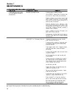
7.9 TROUBLESHOOTING GUIDE (I) (CONTINUED)
SYMPTOM
PROBABLE CAUSE
REMEDY
COMPRESSOR SHUTS DOWN
WITH AIR DEMAND PRESENT
(CONTINUED)
Excessive Operating Pressure
HIGH TEMP T1 or T3 Message Displayed
Check maximum P2 pressure setting.
HIGH PRESS P1 display; Max P1 pressure may
be set too low. Consult factory for recalibration.
Defective solenoid valve; solenoid valve should
cause Sullicon Control lever to move to unload
stop when the unload pressure setting P2A is
exceeded. Repair if defective.
Defective blowdown valve; blowdown valve
should exhaust sump pressure to 30 psig (2.1 bar)
for integrated coolers; 50 psig (3.4 bar) for remote
coolers when maximum operating pressure is
reached. Repair if defective.
Open or shorted P1, P2, P3 or P4 sender mes-
sage; replace sender indicated.
Operating lever of inlet butterfly valve is loose on
valve shaft. Reposition the valve plate and tighten
lever set screw.
Cooling water temperature too high; increase
water flow (water-cooled only).
Cooling water flow insufficient; check water lines,
valves (water-cooled only) and available water
pressure differential.
Cooler plugged; clean tubes. If plugging persists,
install water conditioner or water filter(water-
cooled only).
Cooling air flow restricted; clean cooler and check
for proper ventilation.
Ambient temperature is too high; provide suffi-
cient ventilation.
Cooling air ductwork, if installed, may restrict air
flow. High static fan must be specified with cus-
tomer-supplied ductwork, and ductwork must be
sized to minimize flow restriction.
Low fluid level; add fluid.
Clogged filter; change the fluid filter element as
indicated by Supervisor control.
Thermal valve not functioning properly; replace
element (air-cooled only).
Optional Water flow regulating valve not function-
ing properly; change (water-cooled only).
Open or shorted T1 or T2 sender; check for a
short or open circuit to probe and correct wiring.
Excessive pressure drop in supply and return
lines of remote air-cooled cooling package.
Consult paragraph 4.6 of this manual.
(I)
Consult the Supervisor Controller manual for additional aid to troubleshooting.
Summary of Contents for TS-32S
Page 16: ...Section 2 DESCRIPTION 10 Figure 2 3A Compressor Cooling and Lubrication System Air cooled...
Page 17: ...Section 2 DESCRIPTION 11 Figure 2 3B Compressor Cooling and Lubrication System Water cooled...
Page 18: ...Section 2 DESCRIPTION 12 Figure 2 4A Compressor Discharge System Air cooled...
Page 19: ...Section 2 DESCRIPTION 13 Figure 2 4B Compressor Discharge System Water cooled...
Page 20: ...Section 2 DESCRIPTION 14 Figure 2 5A Control System START Typical...
Page 21: ...Section 2 DESCRIPTION 15 Figure 2 5B Control System MODULATION Typical...
Page 22: ...Section 2 DESCRIPTION 16 Figure 2 5C Control System UNLOAD Typical...
Page 23: ...Section 2 DESCRIPTION 17 Figure 2 5D Control System FULL LOAD Typical...
Page 27: ...Section 3 SPECIFICATIONS 21 NOTES...
Page 40: ...34 NOTES...
Page 48: ...42 NOTES...
Page 60: ...54 NOTES...
Page 63: ...57 NOTES...
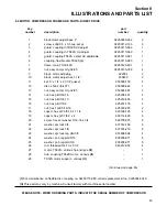
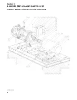
Page 72: ...Section 8 ILLUSTRATIONS AND PARTS LIST 66 8 5 AIR INLET SYSTEM 02250135 499R01...
Page 114: ...Section 8 ILLUSTRATIONS AND PARTS LIST 108 02250135 534R03 8 20 SUMP AND PARTS...
Page 116: ...Section 8 ILLUSTRATIONS AND PARTS LIST 110 02250135 534R03 8 20 SUMP AND PARTS...
Page 118: ...Section 8 ILLUSTRATIONS AND PARTS LIST 112 02250134 158R00 8 21 SULLICON CONTROL...
Page 120: ...Section 8 ILLUSTRATIONS AND PARTS LIST 114 8 22 COMPRESSOR SPIRIAL VALVE ACTUATOR...
Page 124: ...Section 8 ILLUSTRATIONS AND PARTS LIST 118 02250135 643R05 8 24 PNEUMATIC CONTROLS...
Page 126: ...Section 8 ILLUSTRATIONS AND PARTS LIST 120 02250135 643R05 8 24 PNEUMATIC CONTROLS...
Page 128: ...Section 8 ILLUSTRATIONS AND PARTS LIST 122 02250135 643R05 8 24 PNEUMATIC CONTROLS...
Page 134: ...Section 8 ILLUSTRATIONS AND PARTS LIST 128 8 27 CONTROL BOX WYE DELTA TYPICAL 02250122 516R08...
Page 140: ...Section 8 ILLUSTRATIONS AND PARTS LIST 134 02250133 674R04 8 30 ENCLOSURE AIR COOLED...
Page 142: ...Section 8 ILLUSTRATIONS AND PARTS LIST 136 02250133 674R04 8 30 ENCLOSURE AIR COOLED...
Page 144: ...Section 8 ILLUSTRATIONS AND PARTS LIST 138 02250133 675R04 8 31 ENCLOSURE WATER COOLED...
Page 146: ...Section 8 ILLUSTRATIONS AND PARTS LIST 140 02250133 675R04 8 31 ENCLOSURE WATER COOLED...
Page 148: ...Section 8 ILLUSTRATIONS AND PARTS LIST 142 8 32 DECALS...
Page 150: ...Section 8 ILLUSTRATIONS AND PARTS LIST 144 8 32 DECALS...
Page 152: ...Section 8 ILLUSTRATIONS AND PARTS LIST 146 8 32 DECALS...
Page 154: ...Section 8 ILLUSTRATIONS AND PARTS LIST 148 8 33 DECAL LOCATIONS...
Page 156: ...Section 8 ILLUSTRATIONS AND PARTS LIST 150 8 34 DECAL LOCATIONS AIR COOLED ENCLOSURE TYPICAL...
Page 158: ...Section 8 ILLUSTRATIONS AND PARTS LIST 152 8 35 DECAL LOCATIONS WATER COOLED ENCLOSURE TYPICAL...
Page 160: ...Section 8 ILLUSTRATIONS AND PARTS LIST 154 8 36 DECAL LOCATIONS CONTROL BOX...
Page 162: ...Section 8 ILLUSTRATIONS AND PARTS LIST 156 8 37 DECAL LOCATIONS AFTER COOLER...
Page 171: ...NOTES...

