Section 7
MAINTENANCE
53
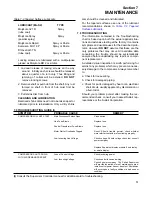
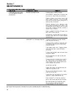
7.9 TROUBLESHOOTING GUIDE (I) (CONTINUED)
SYMPTOM
PROBABLE CAUSE
REMEDY
COMPRESSOR SHUTS DOWN
WITH AIR DEMAND PRESENT
(CONTINUED)
COMPRESSOR WILL NOT BUILD
UP FULL DISCHARGE PRESSURE
LINE PRESSURE RISES ABOVE
UNLOAD P2 PRESSURE SETTING
ON THE SUPERVISOR
EXCESSIVE FLUID CONSUMP-
TION
PRESSURE RELIEF VALVE
OPENS REPEATEDLY
LIQUID WATER IN COMPRESSED
AIR SERVICE LINE
Low Fluid Pressure
(LOW PRESSURE P3 display)
Low Water Pressure
(FAN OL/LOW WATER display)
Air Demand is Too Great
Dirty Air Filter
Pressure Regulator Out of Adjustment
Defective Pressure Regulator
Broken Sullicon Spring
Leak in Control System Causing Loss of
Pressure Signals
Defective Solenoid Valve
Defective Blowdown Valve
Ruptured Sullicon Control Diaphragm
Plugged Control Line Filter
Clogged Return Line Strainer or Orifice
Separator Element Damaged or Not
Functioning Properly
Leak in the Lubrication System
Excess Fluid Foaming
Fluid Level Too High
Defective Pressure Relief Valve
Water Vapor Condensation From Cooling
and Compression Occurs Naturally
Check fluid level.
Check for clogged fluid filter.
Check the cooling fan motor or water flow sys-
tem.
Check service lines for leaks or open valves.
Check for filter maintenance message on supervi-
sor panel and change or clean element if
required.
Adjust regulator according to control adjustment
instructions in the Maintenance Section.
Check diaphragm and replace if necessary (kit
available).
Replace.
Check for leaks.
Check that Sullicon Control lever is moved to
unload stop when Supervisor is in NO LOAD
mode. Repair or replace if necessary (kit avail-
able).
Check that sump pressure is exhausted to the
atmosphere when in the OFF LOAD mode.
Repair or replace if necessary (kit available).
Replace.
Clean or repair if necessary.
Clean strainer (screen with o-ring replacement kit
available)
Clean orifice.
Check Separator Differential (plugged) dP1.
Change Separator
Check all pipes, connections and components.
Drain and change.
Drain excess fluid.
Replace pressure relief valve.
Remove the water vapor from compressed air
prior to distribution through the air system. Check
operation of aftercooler and moisture separator.
Install a compressed air dryer sized for the flow
and dryness level required. (Note: Filters may also
be required to remove particulates, liquid oil
aerosols or for oil vapor removal. Change car-
tridges as recommended by the filter manufactur-
er.) Check all drain traps routinely to insure their
proper operation. Maintain them regularly.
(I)
Consult the Supervisor Controller manual for additional aid to troubleshooting.
Summary of Contents for TS-32S
Page 16: ...Section 2 DESCRIPTION 10 Figure 2 3A Compressor Cooling and Lubrication System Air cooled...
Page 17: ...Section 2 DESCRIPTION 11 Figure 2 3B Compressor Cooling and Lubrication System Water cooled...
Page 18: ...Section 2 DESCRIPTION 12 Figure 2 4A Compressor Discharge System Air cooled...
Page 19: ...Section 2 DESCRIPTION 13 Figure 2 4B Compressor Discharge System Water cooled...
Page 20: ...Section 2 DESCRIPTION 14 Figure 2 5A Control System START Typical...
Page 21: ...Section 2 DESCRIPTION 15 Figure 2 5B Control System MODULATION Typical...
Page 22: ...Section 2 DESCRIPTION 16 Figure 2 5C Control System UNLOAD Typical...
Page 23: ...Section 2 DESCRIPTION 17 Figure 2 5D Control System FULL LOAD Typical...
Page 27: ...Section 3 SPECIFICATIONS 21 NOTES...
Page 40: ...34 NOTES...
Page 48: ...42 NOTES...
Page 60: ...54 NOTES...
Page 63: ...57 NOTES...
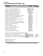
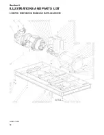
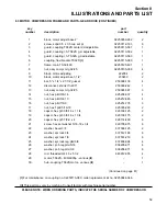
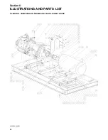
Page 72: ...Section 8 ILLUSTRATIONS AND PARTS LIST 66 8 5 AIR INLET SYSTEM 02250135 499R01...
Page 114: ...Section 8 ILLUSTRATIONS AND PARTS LIST 108 02250135 534R03 8 20 SUMP AND PARTS...
Page 116: ...Section 8 ILLUSTRATIONS AND PARTS LIST 110 02250135 534R03 8 20 SUMP AND PARTS...
Page 118: ...Section 8 ILLUSTRATIONS AND PARTS LIST 112 02250134 158R00 8 21 SULLICON CONTROL...
Page 120: ...Section 8 ILLUSTRATIONS AND PARTS LIST 114 8 22 COMPRESSOR SPIRIAL VALVE ACTUATOR...
Page 124: ...Section 8 ILLUSTRATIONS AND PARTS LIST 118 02250135 643R05 8 24 PNEUMATIC CONTROLS...
Page 126: ...Section 8 ILLUSTRATIONS AND PARTS LIST 120 02250135 643R05 8 24 PNEUMATIC CONTROLS...
Page 128: ...Section 8 ILLUSTRATIONS AND PARTS LIST 122 02250135 643R05 8 24 PNEUMATIC CONTROLS...
Page 134: ...Section 8 ILLUSTRATIONS AND PARTS LIST 128 8 27 CONTROL BOX WYE DELTA TYPICAL 02250122 516R08...
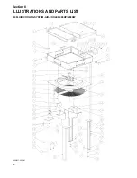
Page 140: ...Section 8 ILLUSTRATIONS AND PARTS LIST 134 02250133 674R04 8 30 ENCLOSURE AIR COOLED...
Page 142: ...Section 8 ILLUSTRATIONS AND PARTS LIST 136 02250133 674R04 8 30 ENCLOSURE AIR COOLED...
Page 144: ...Section 8 ILLUSTRATIONS AND PARTS LIST 138 02250133 675R04 8 31 ENCLOSURE WATER COOLED...
Page 146: ...Section 8 ILLUSTRATIONS AND PARTS LIST 140 02250133 675R04 8 31 ENCLOSURE WATER COOLED...
Page 148: ...Section 8 ILLUSTRATIONS AND PARTS LIST 142 8 32 DECALS...
Page 150: ...Section 8 ILLUSTRATIONS AND PARTS LIST 144 8 32 DECALS...
Page 152: ...Section 8 ILLUSTRATIONS AND PARTS LIST 146 8 32 DECALS...
Page 154: ...Section 8 ILLUSTRATIONS AND PARTS LIST 148 8 33 DECAL LOCATIONS...
Page 156: ...Section 8 ILLUSTRATIONS AND PARTS LIST 150 8 34 DECAL LOCATIONS AIR COOLED ENCLOSURE TYPICAL...
Page 158: ...Section 8 ILLUSTRATIONS AND PARTS LIST 152 8 35 DECAL LOCATIONS WATER COOLED ENCLOSURE TYPICAL...
Page 160: ...Section 8 ILLUSTRATIONS AND PARTS LIST 154 8 36 DECAL LOCATIONS CONTROL BOX...
Page 162: ...Section 8 ILLUSTRATIONS AND PARTS LIST 156 8 37 DECAL LOCATIONS AFTER COOLER...
Page 171: ...NOTES...


