Section 8
ILLUSTRATIONS AND PARTS LIST
59
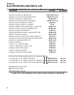
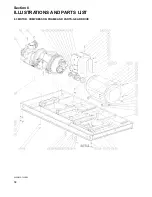
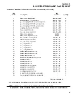
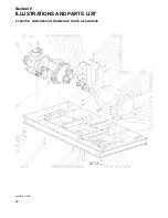
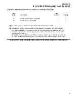
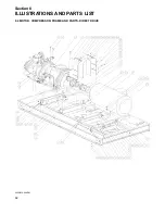
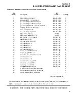
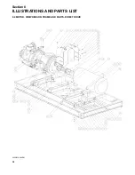
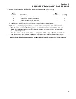
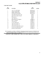
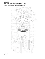
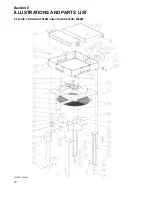
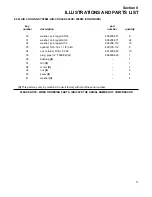
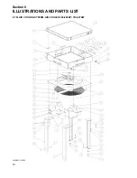
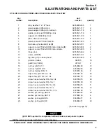
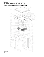
8.3 MOTOR, COMPRESSOR, FRAME AND PARTS- GEAR DRIVE (CONTINUED)
key
part
number
description
number
quantity
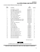
1
block, motor adjust base 2”
02250059-262
2
2
screw, sqhd 0.5 x 3.5 cup set pt
02250112-193
6
3
guard, coupling TS32S center dd adjustable
02250113-561
1
4
guard, coupling l.h. TS32S g.d. adjustable
02250113-562
1
5
guard, coupling r.h. TS32S g.d adjustable
02250113-563
1
6
coupling, flexible disc TS32S
(I)
02250115-080
1
7
frame, main TS32-400
02250125-491
1
8
nut, assy compr mtg 32/25
02250135-358
4
9
block, motor adjusting
222054
2
10
block, motor adjust bse 1-1/2”
230450
2
11
bar, 5” x 1/4” x 27-1/4”gusset
250008-139
4
12
disconnect, shrink rfn-4071
250009-242
1
13
nut, assy compr mtg 32/25
250024-587
3
14
nut, hex pltd 3/8-16
825206-337
4
15
nut, hex pltd 3/4-10
825212-665
4
16
nut, hex pltd 7/8-9
825214-776
3
17
nut, hex f pltd 5/16-18
825305-283
2
18
capscr, hex gr5 3/8-16 x 1 1/4
829106-125
2
19
capscr, hex gr5 3/8-16 x 1 3/4
829106-175
2
20
capscr, hex gr5 7/8-9 x 4
829114-400
6
21
screw, hex ser washer 5/16-18 x 3/4
829705-075
6
22
washer, bevel 3/8
837006-125
2
23
washer, spr lock 3/4
837512-188
8
24
washer, spr lock 7/8
837514-219
6
25
washer, spr lock reg pltd 3/8
837806-094
4
26
washer, pl-b reg pltd 5/16
838205-071
4
27
washer, pl-b reg pltd 3/8
838206-071
6
28
rod, threaded 3/4-10 x 5 1/2
843912-055
4
29
motor, TS32S - 400/600hp - various
(II)
-
1
30
hub, coupling TS32S motor - various
(II)
-
1
(Continued on page 61)
(I)
For maintenance on coupling no. 02250115-080, order replacement kit no. 02250044-346.
(II)
This part may vary by machine. Consult factory with machine serial number.
PLEASE NOTE: WHEN ORDERING PARTS, INDICATE THE SERIAL NUMBER OF COMPRESSOR
Summary of Contents for TS-32S
Page 16: ...Section 2 DESCRIPTION 10 Figure 2 3A Compressor Cooling and Lubrication System Air cooled...
Page 17: ...Section 2 DESCRIPTION 11 Figure 2 3B Compressor Cooling and Lubrication System Water cooled...
Page 18: ...Section 2 DESCRIPTION 12 Figure 2 4A Compressor Discharge System Air cooled...
Page 19: ...Section 2 DESCRIPTION 13 Figure 2 4B Compressor Discharge System Water cooled...
Page 20: ...Section 2 DESCRIPTION 14 Figure 2 5A Control System START Typical...
Page 21: ...Section 2 DESCRIPTION 15 Figure 2 5B Control System MODULATION Typical...
Page 22: ...Section 2 DESCRIPTION 16 Figure 2 5C Control System UNLOAD Typical...
Page 23: ...Section 2 DESCRIPTION 17 Figure 2 5D Control System FULL LOAD Typical...
Page 27: ...Section 3 SPECIFICATIONS 21 NOTES...
Page 40: ...34 NOTES...
Page 48: ...42 NOTES...
Page 60: ...54 NOTES...
Page 63: ...57 NOTES...
Page 72: ...Section 8 ILLUSTRATIONS AND PARTS LIST 66 8 5 AIR INLET SYSTEM 02250135 499R01...
Page 114: ...Section 8 ILLUSTRATIONS AND PARTS LIST 108 02250135 534R03 8 20 SUMP AND PARTS...
Page 116: ...Section 8 ILLUSTRATIONS AND PARTS LIST 110 02250135 534R03 8 20 SUMP AND PARTS...
Page 118: ...Section 8 ILLUSTRATIONS AND PARTS LIST 112 02250134 158R00 8 21 SULLICON CONTROL...
Page 120: ...Section 8 ILLUSTRATIONS AND PARTS LIST 114 8 22 COMPRESSOR SPIRIAL VALVE ACTUATOR...
Page 124: ...Section 8 ILLUSTRATIONS AND PARTS LIST 118 02250135 643R05 8 24 PNEUMATIC CONTROLS...
Page 126: ...Section 8 ILLUSTRATIONS AND PARTS LIST 120 02250135 643R05 8 24 PNEUMATIC CONTROLS...
Page 128: ...Section 8 ILLUSTRATIONS AND PARTS LIST 122 02250135 643R05 8 24 PNEUMATIC CONTROLS...
Page 134: ...Section 8 ILLUSTRATIONS AND PARTS LIST 128 8 27 CONTROL BOX WYE DELTA TYPICAL 02250122 516R08...
Page 140: ...Section 8 ILLUSTRATIONS AND PARTS LIST 134 02250133 674R04 8 30 ENCLOSURE AIR COOLED...
Page 142: ...Section 8 ILLUSTRATIONS AND PARTS LIST 136 02250133 674R04 8 30 ENCLOSURE AIR COOLED...
Page 144: ...Section 8 ILLUSTRATIONS AND PARTS LIST 138 02250133 675R04 8 31 ENCLOSURE WATER COOLED...
Page 146: ...Section 8 ILLUSTRATIONS AND PARTS LIST 140 02250133 675R04 8 31 ENCLOSURE WATER COOLED...
Page 148: ...Section 8 ILLUSTRATIONS AND PARTS LIST 142 8 32 DECALS...
Page 150: ...Section 8 ILLUSTRATIONS AND PARTS LIST 144 8 32 DECALS...
Page 152: ...Section 8 ILLUSTRATIONS AND PARTS LIST 146 8 32 DECALS...
Page 154: ...Section 8 ILLUSTRATIONS AND PARTS LIST 148 8 33 DECAL LOCATIONS...
Page 156: ...Section 8 ILLUSTRATIONS AND PARTS LIST 150 8 34 DECAL LOCATIONS AIR COOLED ENCLOSURE TYPICAL...
Page 158: ...Section 8 ILLUSTRATIONS AND PARTS LIST 152 8 35 DECAL LOCATIONS WATER COOLED ENCLOSURE TYPICAL...
Page 160: ...Section 8 ILLUSTRATIONS AND PARTS LIST 154 8 36 DECAL LOCATIONS CONTROL BOX...
Page 162: ...Section 8 ILLUSTRATIONS AND PARTS LIST 156 8 37 DECAL LOCATIONS AFTER COOLER...
Page 171: ...NOTES...


