Section 8
ILLUSTRATIONS AND PARTS LIST
91
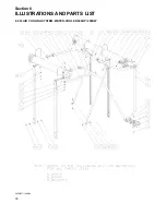
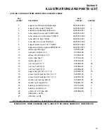
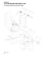
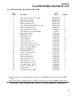
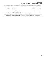
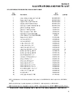
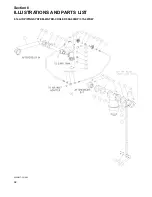
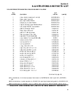
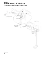
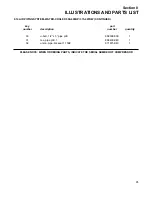
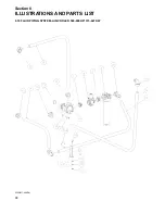
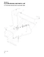
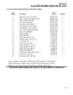
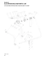
8.13 AIR PIPING SYSTEM- WATER-COOLED 400HP/ 298KW
key
part
number
description
number
quantity
1
valve, minimum pressure 4” w/ck
(I)
02250050-630
1
2
flange, split 4” sae j518
02250105-533
1
3
support, after cooler TS32-400
02250129-208
1
4
adapter, aftrclr TS32SC 400 wc
02250133-183
1
5
adptr, mpv to aftrclr TS32SC 400 wc
02250133-184
1
6
gasket, asa flange 150# 4”
240621-010
3
7
gasket, 4” 125# flg full face
242437-010
1
8
hose, med press 1.00 x .068”
249616-015
2
9
separator, 4” comb trap-4st
(II)
250000-511
1
10
valve, blwdwn 1”nc 2way #c6654
(III)
409783
2
11
flange, thrd 4” 150# rf
819315-064
1
12
nut, hex pltd 1/2-13
825208-448
4
13
nut, hex pltd 5/8-11
825210-559
28
14
o-ring, viton 4 3/8 x 1/8”
826502-245
1
15
o-ring, viton 5 3/8 x 1/8”
826502-253
1
16
capscr, hex gr5 1/2-13 x 2
829108-200
4
17
capscr, hex gr5 5/8-11 x 3 1/4
829110-325
24
18
washer, spr lock reg pltd 1/2
837808-125
6
19
washer, spr lock reg pltd 5/8
837810-156
28
20
stud, threaded 5/8-11 x 3
839410-030
4
21
connector, 37 fl/mpt pltd 1 x 1
860116-100
3
22
elbow, 37fl 90m 1 x 1
860216-100
1
23
elbow, pipe 90 deg plt 1”
866215-040
1
24
nipple, pipe-xs plt 1 x cl
866416-000
3
25
nipple, pipe-xs plt 1 x 2 1/2
866416-025
2
26
nipple, pipe-xs plt 1 1/4 x cl
866420-000
1
27
tee, reducing pltd 1 1/4 x 1 x 1
867505-044
1
28
u-bolt, 1/2” x 5” pipe pltd
868308-500
1
29
tee, pipe pltd 1
868430-040
1
30
union, pipe-brs seat 1 150#
871615-040
1
(I)
For maintenance on minimum pressure check valve no. 02250050-630, order repair kit no. 02250050-
633.
(II)
For maintenance on water separator no. 250000-511, order repair kit no. 250033-036.
(III)
For maintenance on blowdown valve no. 409783 , order repair kit no. 001677
(NOTE:
quantity of two).
PLEASE NOTE: WHEN ORDERING PARTS, INDICATE THE SERIAL NUMBER OF COMPRESSOR
Summary of Contents for TS-32S
Page 16: ...Section 2 DESCRIPTION 10 Figure 2 3A Compressor Cooling and Lubrication System Air cooled...
Page 17: ...Section 2 DESCRIPTION 11 Figure 2 3B Compressor Cooling and Lubrication System Water cooled...
Page 18: ...Section 2 DESCRIPTION 12 Figure 2 4A Compressor Discharge System Air cooled...
Page 19: ...Section 2 DESCRIPTION 13 Figure 2 4B Compressor Discharge System Water cooled...
Page 20: ...Section 2 DESCRIPTION 14 Figure 2 5A Control System START Typical...
Page 21: ...Section 2 DESCRIPTION 15 Figure 2 5B Control System MODULATION Typical...
Page 22: ...Section 2 DESCRIPTION 16 Figure 2 5C Control System UNLOAD Typical...
Page 23: ...Section 2 DESCRIPTION 17 Figure 2 5D Control System FULL LOAD Typical...
Page 27: ...Section 3 SPECIFICATIONS 21 NOTES...
Page 40: ...34 NOTES...
Page 48: ...42 NOTES...
Page 60: ...54 NOTES...
Page 63: ...57 NOTES...
Page 72: ...Section 8 ILLUSTRATIONS AND PARTS LIST 66 8 5 AIR INLET SYSTEM 02250135 499R01...
Page 114: ...Section 8 ILLUSTRATIONS AND PARTS LIST 108 02250135 534R03 8 20 SUMP AND PARTS...
Page 116: ...Section 8 ILLUSTRATIONS AND PARTS LIST 110 02250135 534R03 8 20 SUMP AND PARTS...
Page 118: ...Section 8 ILLUSTRATIONS AND PARTS LIST 112 02250134 158R00 8 21 SULLICON CONTROL...
Page 120: ...Section 8 ILLUSTRATIONS AND PARTS LIST 114 8 22 COMPRESSOR SPIRIAL VALVE ACTUATOR...
Page 124: ...Section 8 ILLUSTRATIONS AND PARTS LIST 118 02250135 643R05 8 24 PNEUMATIC CONTROLS...
Page 126: ...Section 8 ILLUSTRATIONS AND PARTS LIST 120 02250135 643R05 8 24 PNEUMATIC CONTROLS...
Page 128: ...Section 8 ILLUSTRATIONS AND PARTS LIST 122 02250135 643R05 8 24 PNEUMATIC CONTROLS...
Page 134: ...Section 8 ILLUSTRATIONS AND PARTS LIST 128 8 27 CONTROL BOX WYE DELTA TYPICAL 02250122 516R08...
Page 140: ...Section 8 ILLUSTRATIONS AND PARTS LIST 134 02250133 674R04 8 30 ENCLOSURE AIR COOLED...
Page 142: ...Section 8 ILLUSTRATIONS AND PARTS LIST 136 02250133 674R04 8 30 ENCLOSURE AIR COOLED...
Page 144: ...Section 8 ILLUSTRATIONS AND PARTS LIST 138 02250133 675R04 8 31 ENCLOSURE WATER COOLED...
Page 146: ...Section 8 ILLUSTRATIONS AND PARTS LIST 140 02250133 675R04 8 31 ENCLOSURE WATER COOLED...
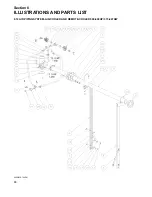
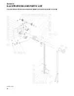
Page 148: ...Section 8 ILLUSTRATIONS AND PARTS LIST 142 8 32 DECALS...
Page 150: ...Section 8 ILLUSTRATIONS AND PARTS LIST 144 8 32 DECALS...
Page 152: ...Section 8 ILLUSTRATIONS AND PARTS LIST 146 8 32 DECALS...
Page 154: ...Section 8 ILLUSTRATIONS AND PARTS LIST 148 8 33 DECAL LOCATIONS...
Page 156: ...Section 8 ILLUSTRATIONS AND PARTS LIST 150 8 34 DECAL LOCATIONS AIR COOLED ENCLOSURE TYPICAL...
Page 158: ...Section 8 ILLUSTRATIONS AND PARTS LIST 152 8 35 DECAL LOCATIONS WATER COOLED ENCLOSURE TYPICAL...
Page 160: ...Section 8 ILLUSTRATIONS AND PARTS LIST 154 8 36 DECAL LOCATIONS CONTROL BOX...
Page 162: ...Section 8 ILLUSTRATIONS AND PARTS LIST 156 8 37 DECAL LOCATIONS AFTER COOLER...
Page 171: ...NOTES...


