Section 4
INSTALLATION
37
representative or the representative from whom the
compressor was purchased. To assist in determin-
ing the amount of fluid necessary to fill the piping,
the following chart may be used.
4.7 ELECTRICAL PREPARATION
Interior electrical wiring is performed at the factory.
Required customer wiring is minimal, but should be
by a qualified electrician in compliance with OSHA,
National Electrical Code, and any other applicable
state or local electrical code concerning isolation
switches, fuse disconnects, etc. Sullair provides a
wiring diagram for use by the installer.
A few electrical checks should be made to help
assure that the first start-up will be trouble free.
Lethal shock hazard inside.
Disconnect all power at source, before opening
or servicing starter or control panel.
1. Check incoming voltage. Be sure that the incom-
ing voltage is the same voltage that the com-
pressor was wired for.
2. Check starter and overload heater sizes (see
Electrical Parts in Parts Manual).
3. Check all electrical connections for tightness.
4. “DRY RUN” the electrical controls by disconnect-
ing the three (3) motor leads from the starter.
Pull out the EMERGENCY STOP button on the
control panel and press
.
Since some solid state starters have built-in power moni-
toring, a dry run will only indicate compressor overload
when machine has this type of starter.
5.
Reconnect the three (3) motor leads and jog the
motor for a direction of rotation check, as explained
in Section 4.8.
4.8 MOTOR ROTATION DIRECTION CHECK
After the electrical wiring has been done, it is nec-
essary to check the direction of the motor rotation.
With the control system in MANUAL mode, press
the
and
pads in succession to bump start
the compressor. When looking at the motor from the
end opposite the compressor unit, the shaft should
be turning clockwise on all gear driven models, and
counterclockwise on direct drive models. If the
motor shaft is not turning in the proper direction,
disconnect the power to the starter and exchange
any two of the three power input leads, then re-
check rotation. A “Direction of Rotation” decal is
located on the coupling guard between the motor
and compressor to show proper motor/compressor
rotation.
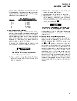
GALLONS/LITERS OF FLUID
PIPE SIZE
PER 12 INCHES/304.8MM OF PIPE
2
.1635/.62
2 1/2
.2555/.97
3 .368/1.39
4
.6542/2.48
6 1.4719/5.57
Summary of Contents for TS-32S
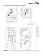
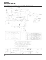
Page 16: ...Section 2 DESCRIPTION 10 Figure 2 3A Compressor Cooling and Lubrication System Air cooled...
Page 17: ...Section 2 DESCRIPTION 11 Figure 2 3B Compressor Cooling and Lubrication System Water cooled...
Page 18: ...Section 2 DESCRIPTION 12 Figure 2 4A Compressor Discharge System Air cooled...
Page 19: ...Section 2 DESCRIPTION 13 Figure 2 4B Compressor Discharge System Water cooled...
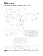
Page 20: ...Section 2 DESCRIPTION 14 Figure 2 5A Control System START Typical...
Page 21: ...Section 2 DESCRIPTION 15 Figure 2 5B Control System MODULATION Typical...
Page 22: ...Section 2 DESCRIPTION 16 Figure 2 5C Control System UNLOAD Typical...
Page 23: ...Section 2 DESCRIPTION 17 Figure 2 5D Control System FULL LOAD Typical...
Page 27: ...Section 3 SPECIFICATIONS 21 NOTES...
Page 40: ...34 NOTES...
Page 48: ...42 NOTES...
Page 60: ...54 NOTES...
Page 63: ...57 NOTES...
Page 72: ...Section 8 ILLUSTRATIONS AND PARTS LIST 66 8 5 AIR INLET SYSTEM 02250135 499R01...
Page 114: ...Section 8 ILLUSTRATIONS AND PARTS LIST 108 02250135 534R03 8 20 SUMP AND PARTS...
Page 116: ...Section 8 ILLUSTRATIONS AND PARTS LIST 110 02250135 534R03 8 20 SUMP AND PARTS...
Page 118: ...Section 8 ILLUSTRATIONS AND PARTS LIST 112 02250134 158R00 8 21 SULLICON CONTROL...
Page 120: ...Section 8 ILLUSTRATIONS AND PARTS LIST 114 8 22 COMPRESSOR SPIRIAL VALVE ACTUATOR...
Page 124: ...Section 8 ILLUSTRATIONS AND PARTS LIST 118 02250135 643R05 8 24 PNEUMATIC CONTROLS...
Page 126: ...Section 8 ILLUSTRATIONS AND PARTS LIST 120 02250135 643R05 8 24 PNEUMATIC CONTROLS...
Page 128: ...Section 8 ILLUSTRATIONS AND PARTS LIST 122 02250135 643R05 8 24 PNEUMATIC CONTROLS...
Page 134: ...Section 8 ILLUSTRATIONS AND PARTS LIST 128 8 27 CONTROL BOX WYE DELTA TYPICAL 02250122 516R08...
Page 140: ...Section 8 ILLUSTRATIONS AND PARTS LIST 134 02250133 674R04 8 30 ENCLOSURE AIR COOLED...
Page 142: ...Section 8 ILLUSTRATIONS AND PARTS LIST 136 02250133 674R04 8 30 ENCLOSURE AIR COOLED...
Page 144: ...Section 8 ILLUSTRATIONS AND PARTS LIST 138 02250133 675R04 8 31 ENCLOSURE WATER COOLED...
Page 146: ...Section 8 ILLUSTRATIONS AND PARTS LIST 140 02250133 675R04 8 31 ENCLOSURE WATER COOLED...
Page 148: ...Section 8 ILLUSTRATIONS AND PARTS LIST 142 8 32 DECALS...
Page 150: ...Section 8 ILLUSTRATIONS AND PARTS LIST 144 8 32 DECALS...
Page 152: ...Section 8 ILLUSTRATIONS AND PARTS LIST 146 8 32 DECALS...
Page 154: ...Section 8 ILLUSTRATIONS AND PARTS LIST 148 8 33 DECAL LOCATIONS...
Page 156: ...Section 8 ILLUSTRATIONS AND PARTS LIST 150 8 34 DECAL LOCATIONS AIR COOLED ENCLOSURE TYPICAL...
Page 158: ...Section 8 ILLUSTRATIONS AND PARTS LIST 152 8 35 DECAL LOCATIONS WATER COOLED ENCLOSURE TYPICAL...
Page 160: ...Section 8 ILLUSTRATIONS AND PARTS LIST 154 8 36 DECAL LOCATIONS CONTROL BOX...
Page 162: ...Section 8 ILLUSTRATIONS AND PARTS LIST 156 8 37 DECAL LOCATIONS AFTER COOLER...
Page 171: ...NOTES...

