background image

Section 7

MAINTENANCE

51

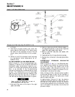
1. Gradual release of locking screws all the way

around.  Initially each screw should be released
about a quarter of a turn only. Thus tilting and
jamming of collars will be avoided. 

DO NOT

remove locking screws.

2. Remove shaft or pull hub from the shaft. Any rust

formed on shaft in front of hub must first be
removed.

3. Pull shrink disc from hub.

CLEANING AND LUBRICATION

Removed shrink discs need not to be taken apart or
lubricated prior to reinstallation. Only a dirty shrink

disc should be cleaned and lubricated.
For the tapered surfaces, use one of the lubricant
recommendations shown in 

Table 7-2 Tapered

Surface Lubricants

.

7.8 TROUBLESHOOTING

The information contained in the Troubleshooting
chart is based upon both the actual applied situa-
tions and extensive testing at the factory. It contains
symptoms and usual causes for the described prob-
lems. However 

DO NOT

assume that these are the

only problems that may occur. All available data
concerning the trouble should be systematically
analyzed before undertaking any repair or compo-
nent replacement.
A detailed visual inspection is worth performing for
almost any problems which may prevent unneces-
sary damage to the compressor. Always remember
to:
a. Check for loose wiring.
b. Check for damaged piping.
c. Check for parts damaged by heat or an electrical

short circuit, usually apparent by discoloration or
a burnt odor.

Should your problem persist after making the rec-
ommended check, consult your nearest Sullair rep-
resentative or the Sullair Corporation.

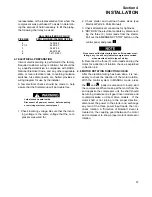
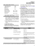
LUBRICANT (MoS2)

TYPE

Molykote 321 R

Spray

(lube coat)
Molykote Spray

Spray

(powder spray)
Molykote G Rapid

Spray or Paste

Aemason MO 19 P

Spray or Paste

DIO-setral 57 N
(lube coat)

Spray or Paste

Locking screws are lubricated with a multipurpose
grease as Molykote BR 2 or similar.

Table 7-2 Tapered Surface Lubricants

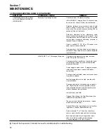
COMPRESSOR WILL NOT START

COMPRESSOR SHUTS DOWN
WITH AIR DEMAND PRESENT

Main Disconnect Switch Open

Line Fuse Blown

Control Transformer Fuse Blown

Motor Starter Overloads Tripped

Low Incoming Line Voltage

Loss of Control Voltage

Low  Incoming Voltage

Close switch.

Replace fuse.

Replace fuse.

Reset. Should trouble persist, check whether
motor starter contacts are functioning properly.

Check voltage. Should voltage check low, consult
power company.

Replace Supervisor display module if no display
or erratic display.

Check incoming power.

Check control fuses and wiring.
Consult power company. The Sullair Supervisor
will provide indication of most maintenance prob-
lems if control power has not been lost. Shutdowns
will occur upon a faulty condition or a bad sender
condition.

7.9 TROUBLESHOOTING GUIDE (I)

SYMPTOM

PROBABLE CAUSE

REMEDY

(I) 

Consult the Supervisor Controller manual for additional aid to troubleshooting.

Summary of Contents for TS-32S

Page 1: ...IAL ROTARY SCREW AIR COMPRESSOR TS 3 32S 400 600HP 298 447KW AIR COOLED WATER COOLED STANDARD AND 24KT KEEP FOR FUTURE REFERENCE Part Number 02250138 002 Sullair Corporation OPERATOR S MANUAL AND PART...

Page 2: ...porate headquarters in Michigan City Indiana Instruction includes discussion of the function and installation of Sullair service parts troubleshooting of the most common problems and actual equipment...

Page 3: ...D LUBRICATION SYSTEM FUNCTIONAL DESCRIPTION 8 2 5 COMPRESSOR DISCHARGE SYSTEM FUNCTIONAL DESCRIPTION 8 2 6 CONTROL SYSTEM FUNCTIONAL DESCRIPTION 18 2 7 AIR INLET SYSTEM FUNCTIONAL DESCRIPTION Section...

Page 4: ...CONTROL PANEL Section 6 COMPRESSOR OPERATION 39 6 1 INTRODUCTION 39 6 2 PURPOSE OF CONTROLS 40 6 3 INITIAL START UP PROCEDURE 41 6 4 SUBSEQUENT START UP PROCEDURE 41 6 5 SHUTDOWN PROCEDURE Section 7 M...

Page 5: ...OLING SYSTEM WATER COOLED 400HP 298KW 80 8 10 FLUID COOLING SYSTEM WATER COOLED 500 600HP 373 447KW 84 8 11 AIR PIPING SYSTEM AIR COOLED 400HP 298KW 86 8 12 AIR PIPING SYSTEM AIR COOLED AND REMOTE COO...

Page 6: ...7KW 134 8 30 ENCLOSURE AIR COOLED 138 8 31 ENCLOSURE WATER COOLED 142 8 32 DECALS 148 8 33 DECAL LOCATIONS 150 8 34 DECAL LOCATIONS AIR COOLED ENCLOSURE 152 8 35 DECAL LOCATIONS WATER COOLED ENCLOSURE...

Page 7: ...trols and or personal hearing protective equipment 1 3 PRESSURE RELEASE A Install an appropriate flow limiting valve between the service air outlet and the shut off throttle valve either at the compre...

Page 8: ...uch as tools away from exposed live electrical parts such as terminals to avoid arcing which might serve as a source of ignition G Remove any acoustical material or other materi al that may be damaged...

Page 9: ...CAL SHOCK A This compressor should be installed and main tained in full compliance with all applicable Federal State and Local codes standards and regulations including those of the National Electrica...

Page 10: ...ssor M Forklift no higher than necessary to clear obsta cles at floor level and transport and corner at mini mum practical speeds N Make sure pallet mounted compressors are firm ly bolted or otherwise...

Page 11: ...compressors are clearly shown The complete package includes compres sor electric motor compressor inlet system compressor discharge system compressor cooling and lubrication system capacity con trol s...

Page 12: ...drive the other which is an idler After the air fluid mixture is discharged from the compressor unit the fluid is separated from the air At this time the air flows to the serv ice line and the fluid...

Page 13: ...Section 2 DESCRIPTION 7 Figure 2 2 Compressor Piping and Instrument Diagram 400 500 600HP 298 373 447KW...

Page 14: ...of fluid remain ing in the compressed air collects on the surface of the nested separator elements primary and sec ondary as the compressed air flows through them Two return lines or scavenge tubes l...

Page 15: ...he rack in turn engages with the pinion mounted on the spiral valve shaft assembly This results in a rotary motion As the spiral valve rotates it starts opening the bypass ports gradually Excess air i...

Page 16: ...Section 2 DESCRIPTION 10 Figure 2 3A Compressor Cooling and Lubrication System Air cooled...

Page 17: ...Section 2 DESCRIPTION 11 Figure 2 3B Compressor Cooling and Lubrication System Water cooled...

Page 18: ...Section 2 DESCRIPTION 12 Figure 2 4A Compressor Discharge System Air cooled...

Page 19: ...Section 2 DESCRIPTION 13 Figure 2 4B Compressor Discharge System Water cooled...

Page 20: ...Section 2 DESCRIPTION 14 Figure 2 5A Control System START Typical...

Page 21: ...Section 2 DESCRIPTION 15 Figure 2 5B Control System MODULATION Typical...

Page 22: ...Section 2 DESCRIPTION 16 Figure 2 5C Control System UNLOAD Typical...

Page 23: ...Section 2 DESCRIPTION 17 Figure 2 5D Control System FULL LOAD Typical...

Page 24: ...of the machine For example an L model rated for 100 psig full load operation and 110 psig unload must have the unload pressure reset to 100 psig This ensures that the motor will not run in an overload...

Page 25: ...EES Remote Heat Recovery Enclosure Phase Monitor Relay Remote Cooler Pack Air cooled Water Solenoid Valve Water Regulator Valve MOTOR Size 400 600hp 298 447kw Consult factory for specific voltages Ty...

Page 26: ...recom mendations A 24KT sample should be sent in annually after the first year 3 4 APPLICATION GUIDE Sullair encourages the user to participate in a fluid analysis program with the fluid suppliers Thi...

Page 27: ...Section 3 SPECIFICATIONS 21 NOTES...

Page 28: ...Section 3 SPECIFICATIONS 22 Figure 3 2A Identification TS 32S 400HP 298KW Typical 02250137 710R00...

Page 29: ...Section 3 SPECIFICATIONS 23 Figure 3 2B Identification TS 32S 500 600HP 373 447KW Typical 02250137 150R02...

Page 30: ...Section 3 SPECIFICATIONS 24 Figure 3 3A Piping and Instrumentation Air cooled 400HP 298KW Typical 02250136 089R01...

Page 31: ...y separator 02250126 325 1 23 gauge pressure 02250117 009 2 24 probe 100 ohm rtd 20 02250044 985 4 25 vlv relief 1 2 150psi 02250092 138 1 26 vlv relief 2 160 02250132 162 1 27 tank fluid sep 02250129...

Page 32: ...Section 3 SPECIFICATIONS 26 Figure 3 3B Piping and Instrumentation Air cooled 500 600HP 373 447KW Typical 02250136 092R02...

Page 33: ...02250078 933 4 16 orifice 094 02250125 776 1 17 glass sight 1 4 02250126 129 2 18 strainer in line sae 02250117 782 2 19 vlv min press check 4 npt 02250050 630 1 20 vlv moisture bleed 41111 1 21 eleme...

Page 34: ...Section 3 SPECIFICATIONS 28 Figure 3 3B Piping and Instrumentation Air cooled 500 600HP 373 447KW Typical 02250136 092R02...

Page 35: ...v ball 1 2 npt 47117 1 40 switch vac 22 w c n4 02250078 249 1 41 drain elec conds scd2400 115 vac 02250131 113 1 42 unit compressor 1 43 vlv sol 3w no 1 4 sequencing 02250125 657 1 44 vlv check 1 4 02...

Page 36: ...Section 3 SPECIFICATIONS 30 Figure 3 3C Piping and Instrumentation Water cooled 400 600HP 298 447KW Typical 02250136 088R02...

Page 37: ...4 16 orifice 094 02250125 776 02250125 776 1 17 glass sight 1 4 02250126 129 02250126 129 2 18 strainer in line sae 02250117 7 2 02250117 782 2 19 vlv min press check 4 npt 02250050 630 02250050 630...

Page 38: ...Section 3 SPECIFICATIONS 32 Figure 3 3C Piping and Instrumentation Water cooled 400 600HP 298 447KW Typical 02250136 088R02...

Page 39: ...vac 22 w c n4 02250078 249 02250078 249 1 41 drain elec conds scd2400 115 vac 02250130 866 02250131 113 1 42 unit compressor 1 43 vlv sol 3w no 1 4 seouencing 02250125 657 02250125 657 1 44 vlv check...

Page 40: ...34 NOTES...

Page 41: ...n The speci fied heat rejection requirement is the amount of heat that is radiated by the compressor This heat must be removed to assure a normal operating tem perature With air cooled compressors it...

Page 42: ...supply and return piping for the fluid cooler must be adequately sized to prevent excessive pressure drop The total pressure drop in the supply and return piping and associated fittings and valves sh...

Page 43: ...trical controls by disconnect ing the three 3 motor leads from the starter Pull out the EMERGENCY STOP button on the control panel and press Since some solid state starters have built in power moni to...

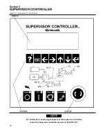
Page 44: ...Section 5 SUPERVISOR CONTROLLER 38 Figure 5 1 Supervisor Control Panel For information concerning all aspects of the Supervisor Controller consult the Supervisor Controller manual no 02250133 517...

Page 45: ...ng this button found on the starter s ther mal overload element housing re closes the starter s con tacts after a current overload takes place Please be aware that the elements must be allowed to cool...

Page 46: ...p side fluid level should be maintained at a level between the high and low sight glass Indicate fluid flow in the separator return lines Large flow should be visible during full load operation little...

Page 47: ...emperature and leaks the following day 6 4 SUBSEQUENT START UP PROCEDURE On subsequent start ups check that the proper level is visible in the fluid sight glass and simply press the START or AUTO MODE...

Page 48: ...42 NOTES...

Page 49: ...AL 50 HOURS OF OPERATION After the initial 50 hours of operation a few mainte nance requirements are needed to rid the system of any foreign materials if any Perform the following maintenance operatio...

Page 50: ...you as to when the primary element maintenance is neces sary When removing the primary element always check the secondary element for visible dirt grease or damage The secondary element must be change...

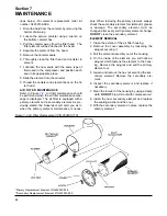
Page 51: ...age is displayed or once a year whichever occurs first Follow the procedure explained below for separator element replace ment PROCEDURE FOR ELEMENT REPLACEMENT 1 Relieve all pressure from the separat...

Page 52: ...ght glass assemblies 2 Unscrew male connector for left side glass or the straight thread tube connector for right side glass from sight glass orifice blocks 3 Remove used filter assembly and replace w...

Page 53: ...r fatigue cracks Discpacks can be checked while coupling is in operation by using a strobe light Replace cracked discpacks and recheck alignment A slight bowing or S like distortion is normal 3 Check...

Page 54: ...e shafts so that a straight edge will rest squarely or within the offset limits specified in Table 7 1 Installation Data on both flanges and at a point 90 away Vertical offset alignment is adjusted by...

Page 55: ...lear the registers on the adapter hubs 2 Place compressed assembly into position If additional compression is required tighten each installation removal bolt on each end an addi tional 1 2 turn 3 Refe...

Page 56: ...d ing Compare the difference to the elongation listed in Table 7 1 Installation Data If required increase or decrease tightening to achieve prop er elongation Repeat this procedure for each drive bolt...

Page 57: ...ping c Check for parts damaged by heat or an electrical short circuit usually apparent by discoloration or a burnt odor Should your problem persist after making the rec ommended check consult your nea...

Page 58: ...ncrease water flow water cooled only Cooling water flow insufficient check water lines valves water cooled only and available water pressure differential Cooler plugged clean tubes If plugging persist...

Page 59: ...open valves Check for filter maintenance message on supervi sor panel and change or clean element if required Adjust regulator according to control adjustment instructions in the Maintenance Section C...

Page 60: ...54 NOTES...

Page 61: ...RESSOR 8 1 PROCEDURE FOR ORDERING PARTS Parts should be ordered from the nearest Sullair Representative or the Representative from whom the com pressor was purchased If for any reason parts cannot be...

Page 62: ...ter kit bolt for drive coupling 02250136 266 1 diaphragm repair kit for spiral valve air cylinder 250016 183 608311 001 1 repair kit for scd 400 electric condensate drain 02250130 866 02250131 044 1 r...

Page 63: ...57 NOTES...

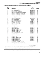
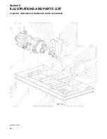
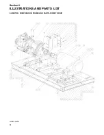
Page 64: ...Section 8 ILLUSTRATIONS AND PARTS LIST 58 8 3 MOTOR COMPRESSOR FRAME AND PARTS GEAR DRIVE 02250135 723R03...

Page 65: ...4 nut hex pltd 3 8 16 825206 337 4 15 nut hex pltd 3 4 10 825212 665 4 16 nut hex pltd 7 8 9 825214 776 3 17 nut hex f pltd 5 16 18 825305 283 2 18 capscr hex gr5 3 8 16 x 1 1 4 829106 125 2 19 capscr...

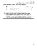
Page 66: ...Section 8 ILLUSTRATIONS AND PARTS LIST 60 8 3 MOTOR COMPRESSOR FRAME AND PARTS GEAR DRIVE 02250135 723R03...

Page 67: ...a remanufactured compressor unit can be obtained from Sullair distributors or the factory at less cost than the owner could repair the unit For information regarding the unit exchange program contact...

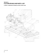
Page 68: ...Section 8 ILLUSTRATIONS AND PARTS LIST 62 8 4 MOTOR COMPRESSOR FRAME AND PARTS DIRECT DRIVE 02250136 899R01...

Page 69: ...14 nut hex pltd 3 8 16 825206 337 4 15 nut hex pltd 3 4 10 825212 665 4 16 nut hex pltd 7 8 9 825214 776 3 17 nut hex f pltd 5 16 18 825305 283 2 18 capscr hex gr5 3 8 16 x 1 1 4 829106 125 4 19 capsc...

Page 70: ...Section 8 ILLUSTRATIONS AND PARTS LIST 64 8 4 MOTOR COMPRESSOR FRAME AND PARTS DIRECT DRIVE 02250136 899R01...

Page 71: ...eby a remanufactured compressor unit can be obtained from Sullair distributors or the factory at less cost than the owner could repair the unit For information regarding the unit exchange program cont...

Page 72: ...Section 8 ILLUSTRATIONS AND PARTS LIST 66 8 5 AIR INLET SYSTEM 02250135 499R01...

Page 73: ...6 2 10 filter 18 dia air I 250006 718 2 11 cap air inlet 10 250007 712 2 12 nut hex f pltd 5 16 18 825305 283 9 13 capscr hex gr5 7 8 9 x 2 829114 200 3 14 capscr hex gr5 7 8 9 x 4 829114 400 8 15 scr...

Page 74: ...Section 8 ILLUSTRATIONS AND PARTS LIST 68 8 6 FLUID COOLING SYSTEM AIR COOLED 400HP 298KW 02250137 202R01...

Page 75: ...2250123 835 2 13 hinge door 02250125 402 4 14 lug lifting clr pk 90deg bend 02250132 040 4 15 grommet rubber 040125 16 16 guard fan 1600q 241347 2 17 nut hex pltd 1 2 13 825208 448 12 18 nut hex f plt...

Page 76: ...Section 8 ILLUSTRATIONS AND PARTS LIST 70 8 6 FLUID COOLING SYSTEM AIR COOLED 400HP 298KW 02250137 202R01...

Page 77: ...38206 071 24 32 washer pl b reg pltd 1 2 838208 112 16 33 eyebolt 5 16 18 x 1 1 8 pltd 839105 112 8 34 nut retainer 5 16 18 092 861405 092 10 35 plug pipe 1 2 3000 stl plt 866900 020 1 36 bushing II 1...

Page 78: ...Section 8 ILLUSTRATIONS AND PARTS LIST 72 8 7 FLUID COOLING SYSTEM AIR COOLED 500 600HP 373 447KW 02250132 133R00...

Page 79: ...bend 02250132 040 4 14 grommet rubber 040125 16 15 guard fan 1600q 241347 2 16 nut hex pltd 1 2 13 825208 448 12 17 nut hex f pltd 5 16 18 825305 283 28 18 nut hex locking 5 16 18 825505 166 8 19 caps...

Page 80: ...Section 8 ILLUSTRATIONS AND PARTS LIST 74 8 7 FLUID COOLING SYSTEM AIR COOLED 500 600HP 373 447KW 02250132 133R00...

Page 81: ...r pl b reg pltd 1 2 838208 112 8 31 eyebolt 5 16 18 x 1 1 8 pltd 839105 112 8 32 nut retainer 5 16 18 092 861405 092 10 33 bushing III 1 34 fan III 1 35 motor III 1 36 nut III 4 37 screw III 4 38 wash...

Page 82: ...Section 8 ILLUSTRATIONS AND PARTS LIST 76 8 8 HORIZONTAL REMOTE COOLER 600HP 447KW 02250135 525R01...

Page 83: ...rc 02250121 121 4 2 frame rem clr 300 400 hp 02210121 124 1 3 panel assembly side 300 400 hp rem clr 02250124 335 4 4 screw self drill 1 4 x 3 4 834504 075 24 5 capscr hex gr5 3 8 16 x 1 1 2 829106 15...

Page 84: ...Section 8 ILLUSTRATIONS AND PARTS LIST 78 8 9 FLUID COOLING SYSTEM WATER COOLED 400HP 298KW 02250137 154R04...

Page 85: ...15 080 1 11 connector tube m 2 x 2 810232 200 2 12 elbow tube 90 deg m 2 x 2 810532 200 4 13 union tube hex 2 811332 200 1 14 nipple pipe 2 x 3 822132 030 1 15 nut hex pltd 1 2 13 825208 448 26 16 nut...

Page 86: ...Section 8 ILLUSTRATIONS AND PARTS LIST 80 8 10 FLUID COOLING SYSTEM WATER COOLED 500 600HP 373 447KW 02250137 343R01...

Page 87: ...2 1 2 x 11 822140 110 1 15 nipple pipe 2 1 2 x 13 1 2 822140 135 2 16 nipple pipe 2 1 2 x 17 1 2 822140 175 1 17 nipple pipe 2 1 2 x 24 1 2 822140 245 1 18 nipple pipe 2 1 2 x 26 822140 260 1 19 nipp...

Page 88: ...Section 8 ILLUSTRATIONS AND PARTS LIST 82 8 10 FLUID COOLING SYSTEM WATER COOLED 500 600HP 373 447KW 02250137 343R01...

Page 89: ...number description number quantity 34 washer spr lock reg pltd 5 8 837810 156 3 35 washer pl b reg pltd 1 2 838208 112 12 36 washer pl b reg pltd 5 8 838210 112 3 37 u bolt 1 2 x 3 pipe pltd 868308 3...

Page 90: ...Section 8 ILLUSTRATIONS AND PARTS LIST 84 8 11 AIR PIPING SYSTEM AIR COOLED 400HP 298KW 02250137 367R01...

Page 91: ...8 11 x 3 1 4 829110 325 16 15 screw hex ser washer 3 8 16 x 3 4 829706 075 4 16 washer spr lock reg pltd 5 8 837810 156 20 17 washer pl b reg pltd 1 2 838208 112 2 18 stud threaded 5 8 11 x 3 839410...

Page 92: ...Section 8 ILLUSTRATIONS AND PARTS LIST 86 8 12 AIR PIPING SYSTEM AIR COOLED AND REMOTE COOLED 500 600HP 373 447KW 02250136 709R01...

Page 93: ...capscr hex gr5 5 8 11 x 3 1 4 829110 325 8 16 screw hex ser washer 1 2 13 x 1 1 4 829708 125 4 17 washer spr lock reg pltd 1 2 837808 125 8 18 washer spr lock reg pltd 5 8 837810 156 12 19 washer pl...

Page 94: ...Section 8 ILLUSTRATIONS AND PARTS LIST 88 8 12 AIR PIPING SYSTEM AIR COOLED AND REMOTE COOLED 500 600HP 373 447KW 02250136 709R01...

Page 95: ...00 600HP 373 447KW CONTINUED key part number description number quantity 31 union pipe brs seat 1 150 871615 040 1 32 flange thrd 4 various III 1 III This part may vary by machine Consult factory with...

Page 96: ...Section 8 ILLUSTRATIONS AND PARTS LIST 90 8 13 AIR PIPING SYSTEM WATER COOLED 400HP 298KW 02250137 255R02...

Page 97: ...hex gr5 1 2 13 x 2 829108 200 4 17 capscr hex gr5 5 8 11 x 3 1 4 829110 325 24 18 washer spr lock reg pltd 1 2 837808 125 6 19 washer spr lock reg pltd 5 8 837810 156 28 20 stud threaded 5 8 11 x 3 8...

Page 98: ...Section 8 ILLUSTRATIONS AND PARTS LIST 92 8 14 AIR PIPING SYSTEM WATER COOLED 500 600HP 373 447KW 02250137 341R03...

Page 99: ...ing viton 5 3 8 x 1 8 826502 253 1 17 capscr hex gr5 1 2 13 x 1 1 2 829108 150 2 18 capscr hex gr5 5 8 11 x 3 1 4 829110 325 24 19 washer spr lock reg pltd 1 2 837808 125 2 20 washer spr lock reg pltd...

Page 100: ...Section 8 ILLUSTRATIONS AND PARTS LIST 94 8 14 AIR PIPING SYSTEM WATER COOLED 500 600HP 373 447KW 02250137 341R03...

Page 101: ...COOLED 500 600HP 373 447KW CONTINUED key part number description number quantity 30 u bolt 1 2 x 5 pipe pltd 868308 500 1 31 tee pipe pltd 1 868430 040 1 32 union pipe brs seat 1 150 871615 040 1 PLE...

Page 102: ...Section 8 ILLUSTRATIONS AND PARTS LIST 96 8 15 FLUID PIPING SYSTEM AIR COOLED 400HP 298KW 02250137 118R00...

Page 103: ...x 2 1 2 811632 250 4 11 connector tube str thd 2 x 2 1 2 811832 250 2 12 nut hex pltd 1 2 13 825208 448 1 13 o ring viton 2 3 4 x 1 8 826502 232 1 14 capscr hex gr5 1 2 13 x 1 1 2 829108 150 1 15 wash...

Page 104: ...Section 8 ILLUSTRATIONS AND PARTS LIST 98 8 16 FLUID PIPING SYSTEM AIR COOLED 500 600HP 373 447KW 02250137 608R01...

Page 105: ...0 1 10 elbow tube str thrd 2 x 2 1 2 811632 250 4 11 connector tube str thd 2 x 2 1 2 811832 250 2 12 nut hex pltd 1 2 13 825208 448 1 13 o ring viton 2 3 4 x 1 8 826502 232 1 14 capscr hex gr5 1 2 13...

Page 106: ...Section 8 ILLUSTRATIONS AND PARTS LIST 100 8 17 FLUID PIPING SYSTEM WATER COOLED 400HP 298KW 02250137 125R00...

Page 107: ...x 2 811332 200 1 12 elbow tube str thrd 2 x 2 1 2 811632 250 2 13 connector tube str thd 2 x 2 1 2 811832 250 4 14 nut hex pltd 1 2 13 825208 448 1 15 o ring viton 2 3 4 x 1 8 826502 232 1 16 capscr h...

Page 108: ...Section 8 ILLUSTRATIONS AND PARTS LIST 102 8 18 FLUID PIPING SYSTEM WATER COOLED 500 600HP 373 447KW 02250137 342R01...

Page 109: ...55 1 10 elbow tube union 2 811232 200 1 11 union tube hex 2 811332 200 1 12 elbow tube str thrd 2 x 2 1 2 811632 250 4 13 connector tube str thd 2 x 2 1 2 811832 250 2 14 nut hex pltd 1 2 13 825208 44...

Page 110: ...Section 8 ILLUSTRATIONS AND PARTS LIST 104 8 19 FLUID PIPING SYSTEM REMOTE COOLED 500 600HP 373 447KW 02250135 799R02...

Page 111: ...1 2 042694 1 15 switch temp n o 115f 043239 1 16 tee reducing 2 x 2 x 1 2 802208 082 1 17 connector tube m 1 2 x 1 2 810208 050 1 18 connector tube m 2 x 2 810232 200 2 19 elbow tube 90 deg m 1 2 x 1...

Page 112: ...Section 8 ILLUSTRATIONS AND PARTS LIST 106 8 19 FLUID PIPING SYSTEM REMOTE COOLED 500 600HP 373 447KW 02250135 799R02...

Page 113: ...ntity 30 washer spr lock reg pltd 1 2 837808 125 7 31 washer pl b reg pltd 1 2 838208 112 3 32 bushing red pltd 1 2 x 1 4 867102 010 1 33 capscrew ferry head hd pltd 1 2 13 x 3 867308 300 4 34 u bolt...

Page 114: ...Section 8 ILLUSTRATIONS AND PARTS LIST 108 02250135 534R03 8 20 SUMP AND PARTS...

Page 115: ...unit 6 ac w 02250137 600 1 16 plug o ring boss sae 1 1 4 040029 2 17 gasket 6 125 flg full face 242437 012 2 18 connector tube f 1 4 x 1 4 810104 025 1 19 connector tube str thd 1 4 x 7 16 811804 044...

Page 116: ...Section 8 ILLUSTRATIONS AND PARTS LIST 110 02250135 534R03 8 20 SUMP AND PARTS...

Page 117: ...bow pipe 90m f 1 4 x 1 4 860704 025 1 29 elbow pipe 90 deg plt 2 866215 080 1 30 nipple pipe xs plt 2 x cl 866432 000 1 31 plug pipe 3 4 3000 stl plt 866900 030 1 32 nipple pipe hx pltd 3 4 x 3 4 8685...

Page 118: ...Section 8 ILLUSTRATIONS AND PARTS LIST 112 02250134 158R00 8 21 SULLICON CONTROL...

Page 119: ...hex pltd 3 8 16 825206 337 7 16 nut hex locking 5 16 18 825505 166 1 17 pin cotter ep sc 1 16 x 3 4 827101 075 1 18 capscrew ferry head hd 3 8 16 x 2 828406 200 1 19 capscr hex gr5 5 16 18 x 2 1 4 829...

Page 120: ...Section 8 ILLUSTRATIONS AND PARTS LIST 114 8 22 COMPRESSOR SPIRIAL VALVE ACTUATOR...

Page 121: ...0 1 14 capscrew hex head gr8 1 4 20 x 1 2 828204 050 4 15 cover adapter 250016 195 1 16 washer regular 8 838201 045 6 17 screw machine rod 8 32 x 1 2 831601 050 6 18 mount air cylinder 250016 188 1 19...

Page 122: ...tion 8 ILLUSTRATIONS AND PARTS LIST 116 8 23A MOISTURE DRAIN 400HP 298KW 02250137 280 8 23B MOISTURE DRAIN 500 600HP 373 447KW 02250137 344 02250137 280R00 500 600HP 373 447KW 400HP 298KW 02250137 344...

Page 123: ...connector tube el 3 8 npt x 1 2 tube 250024 713 1 6 connector tube el 1 2 npt x 1 2 tube 250024 714 2 7 tubing 1 2 thermoplastic 250030 855 2 8 connector tube m 5 16 x 1 4 810205 025 1 9 elbow tube 9...

Page 124: ...Section 8 ILLUSTRATIONS AND PARTS LIST 118 02250135 643R05 8 24 PNEUMATIC CONTROLS...

Page 125: ...tubing supt 02250127 559 1 16 angle support 02250133 550 2 17 bracket support 02250133 551 1 18 bracket supt 02250133 552 1 19 bracket tubing manifold 02250133 564 1 20 valve drain self close 1 8npt 0...

Page 126: ...Section 8 ILLUSTRATIONS AND PARTS LIST 120 02250135 643R05 8 24 PNEUMATIC CONTROLS...

Page 127: ...16 825206 337 5 42 nut hex pltd 1 2 13 825208 448 4 43 nut hex f pltd 5 16 18 825305 283 12 44 capscr hex gr5 3 8 16 x 1 1 2 829106 150 5 45 capscr hex gr5 1 2 13 x 1 1 2 829108 150 4 46 screw hex ser...

Page 128: ...Section 8 ILLUSTRATIONS AND PARTS LIST 122 02250135 643R05 8 24 PNEUMATIC CONTROLS...

Page 129: ...90m f 3 8 x 1 2 860706 050 1 61 tee pipe 150 plt 1 4 866815 010 4 62 plug pipe 1 4 3000 stl plt 866900 010 2 63 bushing red pltd 3 8 x 1 8 867101 005 1 64 nipple pipe hx pltd 3 8 x 1 4 868506 025 1 65...

Page 130: ...Section 8 ILLUSTRATIONS AND PARTS LIST 124 8 25 CONTROL BOX SOLID STATE TYPICAL 02250122 005R04...

Page 131: ...va trans 02250083 189 1 11 power supply 24v 0250120 644 1 12 relay 45496 1 13 relay base 46467 1 14 ground bus 02550110 334 1 15 ground bar 02550101 721 1 16 240A IT starter 02250122 042 1 17 304A IT...

Page 132: ...Section 8 ILLUSTRATIONS AND PARTS LIST 126 8 26 CONTROL BOX FULL VOLTAGE TYPICAL 02250122 511R04...

Page 133: ...trans 02250083 188 1 10 univ 350 va trans 02250083 190 11 primary fuse 4 amp 250026 649 12 secondary fuse 6 a 250019 762 13 ground bus 02550110 334 1 14 ground bar 02550101 721 1 15 display module 02...

Page 134: ...Section 8 ILLUSTRATIONS AND PARTS LIST 128 8 27 CONTROL BOX WYE DELTA TYPICAL 02250122 516R08...

Page 135: ...0089 302 1 12 bezel gasket 02550090 872 1 13 I O module 02550141 089 1 14 display module 02550119 330 1 15 transformer 24v 02250135 283 1 16 size 5 contactor 02250083 824 1 17 size 4 contactor 0255008...

Page 136: ...Section 8 ILLUSTRATIONS AND PARTS LIST 130 02250135 448R03 8 28 INSULATION AIR COOLED 400 600HP 298 447KW...

Page 137: ...nel acoustic foam 3 5 x 63 x 2 02250127 700 1 6 panel acoustic foam 2 x 14 5 x 31 02250128 038 1 7 panel acoustic foam 18 5 x 65 5 x 2 02250135 431 2 8 panel acoustic foam 11 75 x 81 5 x 2 02250135 43...

Page 138: ...Section 8 ILLUSTRATIONS AND PARTS LIST 132 02250135 463R04 8 29 INSULATION WATER COOLED AND REMOTE COOLED 400 600HP 298 447KW...

Page 139: ...4 1 5 panel acoustic foam 3 5 x 63 x 2 02250127 700 1 6 panel acoustic foam 18 5 x 65 5 x 2 02250135 431 4 7 panel acoustic foam 11 75 x 81 5 x 2 02250135 432 3 8 panel acoustic foam 13 x 81 5 x 2 022...

Page 140: ...Section 8 ILLUSTRATIONS AND PARTS LIST 134 02250133 674R04 8 30 ENCLOSURE AIR COOLED...

Page 141: ...17 support canopy cntr post TS32S 02250133 839 2 18 strap bustle support TS32S ac wc 02250133 840 1 19 panel canopy header TS32S 02250134 127 2 20 panel access assy 30 x 57 TS32S w padlock I 02250134...

Page 142: ...Section 8 ILLUSTRATIONS AND PARTS LIST 136 02250133 674R04 8 30 ENCLOSURE AIR COOLED...

Page 143: ...pltd 1 4 20 825104 226 2 37 nut hex f pltd 5 16 18 825305 283 92 38 nut hex locking 5 16 18 825505 166 2 39 capscr hex gr5 1 4 20 x 3 4 829104 075 2 40 capscr hex gr5 5 16 18 x 3 4 829105 075 6 41 sc...

Page 144: ...Section 8 ILLUSTRATIONS AND PARTS LIST 138 02250133 675R04 8 31 ENCLOSURE WATER COOLED...

Page 145: ...opy cntr post TS32S 02250133 839 2 18 strap bustle support TS32S ac wc 02250133 840 1 19 panel canopy header TS32S 02250134 127 4 20 panel access assy 30 x 57 TS32S w padlock latch I 02250134 175 2 21...

Page 146: ...Section 8 ILLUSTRATIONS AND PARTS LIST 140 02250133 675R04 8 31 ENCLOSURE WATER COOLED...

Page 147: ...16 18 x 3 4 829105 075 6 43 capscr hex gr5 7 16 14 x 3 1 2 829107 350 6 44 screw hex ser washer 5 16 18 x 3 4 829705 075 11 45 screw hex ser washer 5 16 18 x 1 829705 100 38 46 screw self drill 1 4 x...

Page 148: ...Section 8 ILLUSTRATIONS AND PARTS LIST 142 8 32 DECALS...

Page 149: ...1 3 sign warning sever fan 049855 2 4 sign danger electrocution 049850 1 5 sign warning food grade lube 250003 144 1 6 decal warning actuator 250029 836 1 7 sign warning compressor fluid fill cap 0496...

Page 150: ...Section 8 ILLUSTRATIONS AND PARTS LIST 144 8 32 DECALS...

Page 151: ...69 389 1 17B decal fluid 24KT 02250069 395 1 17C decal fluid CP 4600 32 F 02250118 342 1 18 decal water drain 250022 810 1 19A decal V 460 3 60 international 02250069 399 1 19B decal V 575 3 60 intern...

Page 152: ...Section 8 ILLUSTRATIONS AND PARTS LIST 146 8 32 DECALS...

Page 153: ...250021 286 1 28 decal ISO 9001 I 1 29 decal fluid sample 250022 675 1 30 decal electrical component ID 250038 457 1 31 sign power energized 249544 049 1 32 sign warning sever fan door closed 02250131...

Page 154: ...Section 8 ILLUSTRATIONS AND PARTS LIST 148 8 33 DECAL LOCATIONS...

Page 155: ...0 decal fluid II 11 sign warning compressor fluid fill cap 049685 1 12 decal warning mixing fluids 02250110 891 1 13 sign warning hot surfaces 407408 3 14 decal warning actuator 250029 836 1 15 decal...

Page 156: ...Section 8 ILLUSTRATIONS AND PARTS LIST 150 8 34 DECAL LOCATIONS AIR COOLED ENCLOSURE TYPICAL...

Page 157: ...ecal TS 32 02250061 379 1 6 decal 24KT I 02250061 022 1 7 decal ISO 9001 II 1 8 decal Sullair logo 02250059 048 2 9 decal fork lifting 241814 4 10 sign air breathing danger 250027 935 1 11 sign warnin...

Page 158: ...Section 8 ILLUSTRATIONS AND PARTS LIST 152 8 35 DECAL LOCATIONS WATER COOLED ENCLOSURE TYPICAL...

Page 159: ...850 1 8 sign warning sever fan 049855 2 9 decal warning auto start 250017 903 1 10 decal autostart 041065 1 11 decal ISO 9001 II 1 12 decal 24KT I 02250061 022 1 13 decal Sullair logo 02250059 048 2 1...

Page 160: ...Section 8 ILLUSTRATIONS AND PARTS LIST 154 8 36 DECAL LOCATIONS CONTROL BOX...

Page 161: ...und 02250075 045 2 2 decal danger high voltage 042218 1 3 decal V 460 3 60 international 02250069 399 1 decal V 575 3 60 international 02250069 400 1 decal V 380 3 50 international 02250069 412 1 deca...

Page 162: ...Section 8 ILLUSTRATIONS AND PARTS LIST 156 8 37 DECAL LOCATIONS AFTER COOLER...

Page 163: ...r quantity 1 sign warning sever fan port 049965 1 2 sign warning sever fan 049855 1 3 decal rotation 250021 564 1 4 sign warning sever fan door closed 02250131 539 4 5 decal Sullair 4 5 x 36 black 022...

Page 164: ...Section 8 ILLUSTRATIONS AND PARTS LIST 158 02250130 732R01 8 38 WIRING DIAGRAM AIR COOLED FULL VOLTAGE...

Page 165: ...Section 8 ILLUSTRATIONS AND PARTS LIST 159 02250130 726R01 8 39 WIRING DIAGRAM WATER COOLED FULL VOLTAGE...

Page 166: ...Section 8 ILLUSTRATIONS AND PARTS LIST 160 02250130 730R02 8 40 WIRING DIAGRAM AIR COOLED WYE DELTA...

Page 167: ...Section 8 ILLUSTRATIONS AND PARTS LIST 161 02250130 728R01 8 41 WIRING DIAGRAM WATER COOLED WYE DELTA...

Page 168: ...Section 8 ILLUSTRATIONS AND PARTS LIST 162 02250130 731R02 8 42 WIRING DIAGRAM AIR COOLED SOLID STATE...

Page 169: ...Section 8 ILLUSTRATIONS AND PARTS LIST 163 02250130 727R02 8 43 WIRING DIAGRAM WATER COOLED SOLID STATE...

Page 170: ...Section 8 ILLUSTRATIONS AND PARTS LIST 164 02250130 723R01 8 44 WIRING DIAGRAM AIR COOLED REMOTE COOLER...

Page 171: ...NOTES...
Page 172: ...LLAIR CORPORATION 3700 East Michigan Boulevard Michigan City Indiana 46360 U S A www sullair com Telephone 1 800 SULLAIR U S A Only or 1 219 879 5451 Fax 219 874 1273 PARTS DEPARTMENT Fax 219 874 1835...

Reviews: