TS32 USER MANUAL
SECTION 3
28
3.3
MOTOR SPECIFICATIONS
3.4
LUBRICATION GUIDE—
STANDARD COMPRESSORS
Refer to
. Sullube fluid should be changed
every 8000 hours or once a year, whichever comes
first. The fluid should be changed more frequently
under severe operating conditions, such as high
ambient temperatures coupled with high humidity, or
when high particulate level, corrosive gases or strong
oxidizing gases are present in the air.
Maintenance of all other components is still
recommended as indicated in the Operator's Manual.
Sullair encourages the user to participate in a fluid
analysis program with the fluid suppliers. This could
result in a fluid change interval differing from that
stated in the manual. Contact your Sullair dealer for
details.
A fluid sample at every 1000 hours is recommended.
For a free Sullube analysis, send fluid to:
Dow Chemical
Lubricant Technology Center
Building B-1605
Freeport, TX 77541
To facilitate this, a sample bottle is included with the
compressor.
MOTOR: (60 Hz Compressors)
STANDARD MODELS:
Size:
200-350HP/150-261Kw- Consult factory for specific voltages
Type:
Open Dripproof enclosure, 3-phase, 50 or 60 hz, 104°F / 40°C Maximum
Ambient Temperature
Options:
Various voltages, TEFC enclosure, CE approved (50 hz), Premium
efficiency
Speed:
1780 RPM (60 hz), 1475 RPM (50 hz)
Starter:
Full-Voltage, Wye-Delta or Solid State
WARNING
Before changing or recharging system fluid
always relieve all pressure from the sump tank
and all compressor lines.
NOTE
Sullair standard compressors are filled with
Sullube fluid as factory fill.
Mixing of other lubricants within the com-
pressor unit will void all warranties.
CAUTION
“The Plastic Pipe Institute recommends against
the use of thermoplastic pipe to transport com-
pressed air or other compressed gases in
exposed above ground locations, e.g. in
exposed plant piping.” (I) PVC piping should
not be used with Sullube. It may affect the
bond at cemented joints. Certain other plastic
materials may also be affected.
(I) Plastic Pipe Institute, Recommendation B,
Adopted January 19, 1972.
Summary of Contents for TS32 AC
Page 10: ...NOTES 10...
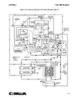
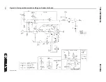
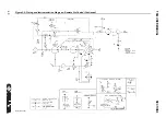
Page 15: ...SECTION 2 TS32 USER MANUAL 15 Figure 2 3 Compressor Piping and Instrument Diagram Typical...
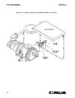
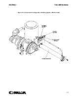
Page 16: ...TS32 USER MANUAL SECTION 2 16 Figure 2 4 Compressor Cooling and Lubrication System Air cooled...
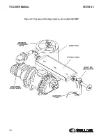
Page 18: ...TS32 USER MANUAL SECTION 2 18 Figure 2 6 Compressor Discharge System Air cooled 200 350HP...
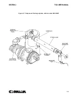
Page 19: ...SECTION 2 TS32 USER MANUAL 19 Figure 2 7 Compressor Discharge System Water cooled 200 350HP...
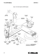
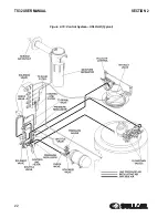
Page 20: ...TS32 USER MANUAL SECTION 2 20 Figure 2 8 Control System START Typical...
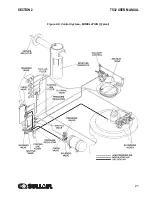
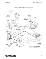
Page 21: ...SECTION 2 TS32 USER MANUAL 21 Figure 2 9 Control System MODULATION Typical...
Page 22: ...TS32 USER MANUAL SECTION 2 22 Figure 2 10 Control System UNLOAD Typical...
Page 23: ...SECTION 2 TS32 USER MANUAL 23 Figure 2 11 Control System FULL LOAD Typical...
Page 26: ...TS32 USER MANUAL SECTION 2 26 Figure 2 12 Compressor Air Inlet System...
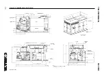
Page 30: ...TS32 USER MANUAL SECTION 3 30 Figure 3 2 Identification Air Cooled 02250126 376 R02...
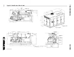
Page 32: ...TS32 USER MANUAL SECTION 3 32 Figure 3 2 Identification Water Cooled 02250126 378 R03...
Page 50: ...TS32 USER MANUAL SECTION 3 50 Figure 3 9 Wiring Diagram Air Cooled SSRV 02250178 844 R03...
Page 54: ...NOTES 54...
Page 78: ...NOTES 78...
Page 79: ...NOTES 79...

