SECTION 6
TS32 USER MANUAL
69
E
LEMENT
R
EMOVAL
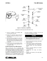
1. Clean the exterior of the air filter housing.
2. Remove the cover assembly by loosening
the wingnut securing it.
3. On the inside you will notice a wingnut which
fastens the element to the housing. Remove
the wingnut and pull the primary element out.
4. Loosen and remove the hex nut securing the
secondary element. Remove the secondary
element.
5. Inspect the secondary element and replace if
necessary.
6. Clean the interior of the housing by using a
damp cloth.
DO NOT
blow dirt out with com-
pressor air.
7. Install the new secondary element and
replace the sealing washer and hex nut.
8. With the secondary element in place, replace
the primary element.
DO NOT
strike the element against any hard surface
to dislodge dust. This will damage the sealing
surfaces and possibly rupture the element.
DO NOT
“blow” dirt out of the interior of the filter
housing. This may introduce dust downstream of the
filter. Instead, use a clean damp cloth.
DO NOT
oil the element.
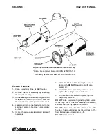
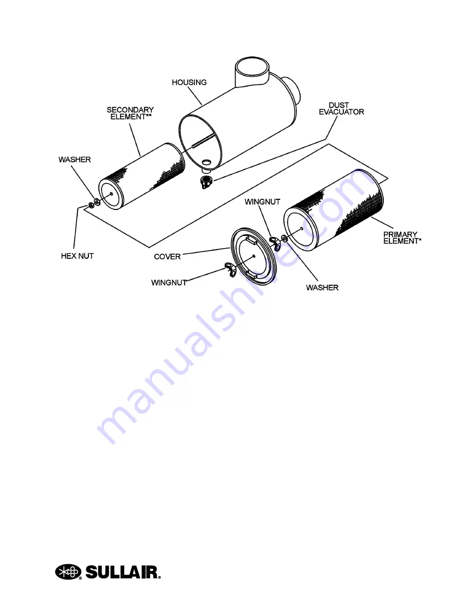
Figure 6-2: Air Filter Replacement (P/N 250006-718)
*Primary Replacement Element Kit P/N 02250135-149
**Secondary Replacement Element Kit P/N 25007-839
Summary of Contents for TS32 AC
Page 10: ...NOTES 10...
Page 15: ...SECTION 2 TS32 USER MANUAL 15 Figure 2 3 Compressor Piping and Instrument Diagram Typical...
Page 16: ...TS32 USER MANUAL SECTION 2 16 Figure 2 4 Compressor Cooling and Lubrication System Air cooled...
Page 18: ...TS32 USER MANUAL SECTION 2 18 Figure 2 6 Compressor Discharge System Air cooled 200 350HP...
Page 19: ...SECTION 2 TS32 USER MANUAL 19 Figure 2 7 Compressor Discharge System Water cooled 200 350HP...
Page 20: ...TS32 USER MANUAL SECTION 2 20 Figure 2 8 Control System START Typical...
Page 21: ...SECTION 2 TS32 USER MANUAL 21 Figure 2 9 Control System MODULATION Typical...
Page 22: ...TS32 USER MANUAL SECTION 2 22 Figure 2 10 Control System UNLOAD Typical...
Page 23: ...SECTION 2 TS32 USER MANUAL 23 Figure 2 11 Control System FULL LOAD Typical...
Page 26: ...TS32 USER MANUAL SECTION 2 26 Figure 2 12 Compressor Air Inlet System...
Page 30: ...TS32 USER MANUAL SECTION 3 30 Figure 3 2 Identification Air Cooled 02250126 376 R02...
Page 32: ...TS32 USER MANUAL SECTION 3 32 Figure 3 2 Identification Water Cooled 02250126 378 R03...
Page 50: ...TS32 USER MANUAL SECTION 3 50 Figure 3 9 Wiring Diagram Air Cooled SSRV 02250178 844 R03...
Page 54: ...NOTES 54...
Page 78: ...NOTES 78...
Page 79: ...NOTES 79...

