Section 2
11
TS32 USER MANUAL
DESCRIPTION
2.1
DESCRIPTION OF
COMPONENTS
(air-cooled) or
(watercooled). The components and assemblies of
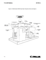
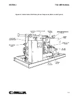
the air compressors are clearly shown. The complete
package includes compressor, electric motor,
compressor inlet system, compressor discharge
system, compressor cooling and lubrication system,
capacity control system, and Supervisor control
system, all mounted on a structural steel frame.
On air-cooled models, a separate motor-driven fan
forces air through the cooler/aftercooler assembly,
thereby removing the heat of compression from the
cooling fluid.
On water-cooled models, fluid is piped into a
fourpass exchanger where the heat of compression
is removed from the fluid. A fan is used to supply
sufficient ventilating air to the compressors equipped
with a canopy.
Both air-cooled and water-cooled versions have
easily accessible items such as the fluid filters and
control valves. The inlet air filters are also mounted
for easy access and servicing.
2.2
SULLAIR COMPRESSOR
UNIT, FUNCTIONAL
DESCRIPTION
Sullair air compressors feature the Sullair
compressor unit, a two-stage, positive displacement,
lubricated-type compressor. This unit provides
continuous pulse-free air compression to meet your
needs. With a Sullair compressor, there is no
maintenance or inspection of the internal parts of the
compressor unit permitted in accordance with the
terms of the warranty.
Fluid is injected into the compressor unit in large
quantities and mixes directly with the air as the rotors
turn, compressing the air. The fluid flow has three
primary functions. It cools, seals and lubricates the
compressor.
Summary of Contents for TS32 AC
Page 10: ...NOTES 10...
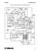
Page 15: ...SECTION 2 TS32 USER MANUAL 15 Figure 2 3 Compressor Piping and Instrument Diagram Typical...
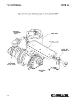
Page 16: ...TS32 USER MANUAL SECTION 2 16 Figure 2 4 Compressor Cooling and Lubrication System Air cooled...
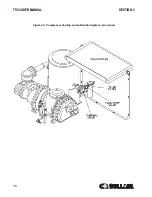
Page 18: ...TS32 USER MANUAL SECTION 2 18 Figure 2 6 Compressor Discharge System Air cooled 200 350HP...
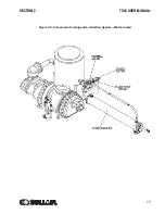
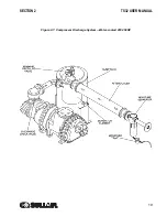
Page 19: ...SECTION 2 TS32 USER MANUAL 19 Figure 2 7 Compressor Discharge System Water cooled 200 350HP...
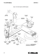
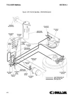
Page 20: ...TS32 USER MANUAL SECTION 2 20 Figure 2 8 Control System START Typical...
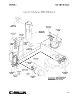
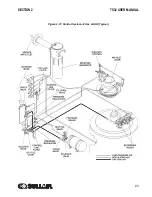
Page 21: ...SECTION 2 TS32 USER MANUAL 21 Figure 2 9 Control System MODULATION Typical...
Page 22: ...TS32 USER MANUAL SECTION 2 22 Figure 2 10 Control System UNLOAD Typical...
Page 23: ...SECTION 2 TS32 USER MANUAL 23 Figure 2 11 Control System FULL LOAD Typical...
Page 26: ...TS32 USER MANUAL SECTION 2 26 Figure 2 12 Compressor Air Inlet System...
Page 30: ...TS32 USER MANUAL SECTION 3 30 Figure 3 2 Identification Air Cooled 02250126 376 R02...
Page 32: ...TS32 USER MANUAL SECTION 3 32 Figure 3 2 Identification Water Cooled 02250126 378 R03...
Page 50: ...TS32 USER MANUAL SECTION 3 50 Figure 3 9 Wiring Diagram Air Cooled SSRV 02250178 844 R03...
Page 54: ...NOTES 54...
Page 78: ...NOTES 78...
Page 79: ...NOTES 79...


