SECTION 2
TS32 USER MANUAL
25
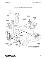
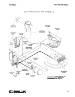
expands the diaphragm. The rack, in turn, engages
with the pinion mounted on the spiral valve shaft
assembly. This results in a rotary motion. As the
spiral valve rotates, it starts opening the bypass ports
gradually. Excess air is then being returned back
internally to suction end of compressor unit. Now the
compressor is fully compressing only that amount of
air which is being used. As air demand keeps
dropping further, the spiral valve keeps opening
more and more until all the bypass ports are fully
open. At this point, the spiral valve has moved into
the minimum position. The spiral valve provides a
modulation range from 100 to approximately 50%.
During this period, the pressure rises approximately
from 100 to 108 psig (6.9 to 7.4 bar). As the air
pressure exceeds 108 psig (7.4 bar), the differential
pressure regulator controlling the Sullicon Control
opens. This allows the air pressure to expand the
diaphragm chamber of the Sullicon Control, which
starts partially closing the inlet butterfly valve. The
inlet butterfly valve provides modulation range from
50 to 40%. During this period, the pressure rises
approximately from 108 to 110 psig (7.4 to 7.6 bar).
During this range, the spiral valve remains in the full
open position.
UNLOAD MODE— IN EXCESS OF 110
PSIG (7.6 BAR)
When a relatively small amount or no air is being
used, the service line pressure continues to rise.
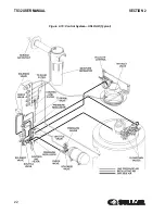
When it exceeds 110 psig (7.6 bar), Supervisor
deenergizes the solenoid valve allowing line
pressure to be supplied directly to the Sullicon
diaphragm keeping the inlet butterfly closed; the
spiral valve is in the fully open (minimum) position.
Simultaneously, the solenoid valve sends a
pneumatic signal to the blowdown valve. The
blowdown valve opens the sump to the atmosphere.
This reduces the sump pressure to approximately 30
psig (2.1 bar) which results in low horsepower
consumption. The check valve in the air service line
prevents line pressure from returning to sump while
the compressor is running in the unloaded mode.
Both the spiral valve and the butterfly valve remain in
the unload position. When the line pressure drops
back to 100 psig (6.9 bar) due to an increase in the
air demand, Supervisor energizes the solenoid valve
allowing the air pressure behind the Sullicon Control
to be vented through the solenoid valve exhaust port.
The blowdown valve closes, and the inlet butterfly
valve opens. Also the air pressure at the spiral valve
actuator diaphragm is reduced through a vent hole at
the spiral valve differential pressure regulator, and a
spring in the actuator causes the spiral valve to
return to the full load (maximum) position.
AUTOMATIC OPERATION
For applications with varied periods of time when
there are no air requirements, Supervisor’s Auto
mode allows the compressor to shut down (time
delayed) when no compressed air requirement is
present and restart as compressed air is needed.
LOAD/ NO LOAD OPERATION
If applications call for load/no load operation,
modulation can be disabled in the Supervisor
ControllerTM in the “Control Parameters” menu. If
modulation is disabled, the unload pressure must be
reset to the rated load pressure of the machine. For
example, an L model rated for 100 psig full load
operation and 110 psig unload must have the unload
pressure reset to 100 psig. This ensures that the
motor will not run in an overload condition.
2.6
AIR INLET SYSTEM,
FUNCTIONAL DESCRIPTION
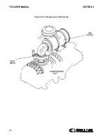
. The compressor inlet system
consists of one or two dry-type air filters, a vacuum
switch and an air inlet valve.
The vacuum switch, located in the compressor
Supervisor control system, indicates the condition of
the air filter. When the message “AIR FILTER MAINT
RQD” is displayed,maintenance is required.
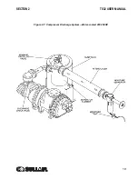
The butterfly-type air inlet valve directly controls the
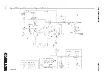
amount of air intake to the compressor in response to
the operation of the Sullicon Control (
).
CAUTION
“The Plastic Pipe Institute recommends against
the use of thermoplastic pipe to transport com-
pressed air or other compressed gases in
exposed above ground locations, e.g. in
exposed plant piping.” (I) PVC piping should
not be used with Sullube. It may affect the
bond at cemented joints. Certain other plastic
materials may also be affected.
(I) Plastic Pipe Institute, Recommendation B,
Adopted January 19, 1972.
Summary of Contents for TS32 AC
Page 10: ...NOTES 10...
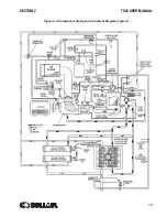
Page 15: ...SECTION 2 TS32 USER MANUAL 15 Figure 2 3 Compressor Piping and Instrument Diagram Typical...
Page 16: ...TS32 USER MANUAL SECTION 2 16 Figure 2 4 Compressor Cooling and Lubrication System Air cooled...
Page 18: ...TS32 USER MANUAL SECTION 2 18 Figure 2 6 Compressor Discharge System Air cooled 200 350HP...
Page 19: ...SECTION 2 TS32 USER MANUAL 19 Figure 2 7 Compressor Discharge System Water cooled 200 350HP...
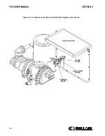
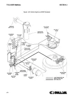
Page 20: ...TS32 USER MANUAL SECTION 2 20 Figure 2 8 Control System START Typical...
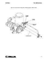
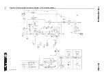
Page 21: ...SECTION 2 TS32 USER MANUAL 21 Figure 2 9 Control System MODULATION Typical...
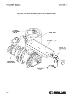
Page 22: ...TS32 USER MANUAL SECTION 2 22 Figure 2 10 Control System UNLOAD Typical...
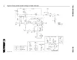
Page 23: ...SECTION 2 TS32 USER MANUAL 23 Figure 2 11 Control System FULL LOAD Typical...
Page 26: ...TS32 USER MANUAL SECTION 2 26 Figure 2 12 Compressor Air Inlet System...
Page 30: ...TS32 USER MANUAL SECTION 3 30 Figure 3 2 Identification Air Cooled 02250126 376 R02...
Page 32: ...TS32 USER MANUAL SECTION 3 32 Figure 3 2 Identification Water Cooled 02250126 378 R03...
Page 50: ...TS32 USER MANUAL SECTION 3 50 Figure 3 9 Wiring Diagram Air Cooled SSRV 02250178 844 R03...
Page 54: ...NOTES 54...
Page 78: ...NOTES 78...
Page 79: ...NOTES 79...

