Section 3
27
TS32 USER MANUAL
SPECIFICATIONS
3.1
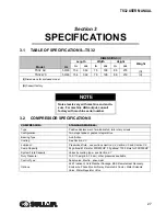
TABLE OF SPECIFICATIONS—TS32
3.2
COMPRESSOR SPECIFICATIONS
Model
Hz
DIMENSIONS (I)
Length
Width
Height
Weight
in
cm
in
cm
in
cm
TS32 AC
50/60
154
392
78
198
86
218
(II)
TS32 WC
50/60
154
392
78
198
86
218
(II)
(I)
Dimensions for enclosed model
(II)
Consult factory.
NOTE
Noise levels vary with machine and enclo-
sure. For machine dBA output, consult
factory with machine serial number.
COMPRESSOR:
STANDARD MODELS:
Type:
Positive displacement, fluid-lubricated, twin rotary screws
Configuration:
Two-stage tandem, geared integral drive
Bearing Type:
Anti-friction
Cooling:
See
Lubricant:
Pressurized fluid - see sections
and
Sump Capacity:
24 gallons/91 liters for 200/250HP, 35 gallons/ 132.5 liters for 300/350HP
System Fluid Capacity:
Varies by cooling type - see
Duty Pressure:
100-110 psig (6.9-7.6 bar), other pressures available
Control Type:
Spiral valve, Electro - pneumatic
Options:
24KT lubricant, Cold Weather Package, EES Remote Heat Recovery,
Enclosure, Phase Monitor Relay, Remote Air Cooler, Water Solenoid
Valve, Water Regulator Valve
Summary of Contents for TS32 AC
Page 10: ...NOTES 10...
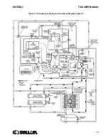
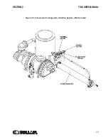
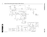
Page 15: ...SECTION 2 TS32 USER MANUAL 15 Figure 2 3 Compressor Piping and Instrument Diagram Typical...
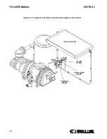
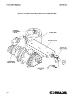
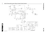
Page 16: ...TS32 USER MANUAL SECTION 2 16 Figure 2 4 Compressor Cooling and Lubrication System Air cooled...
Page 18: ...TS32 USER MANUAL SECTION 2 18 Figure 2 6 Compressor Discharge System Air cooled 200 350HP...
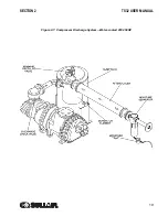
Page 19: ...SECTION 2 TS32 USER MANUAL 19 Figure 2 7 Compressor Discharge System Water cooled 200 350HP...
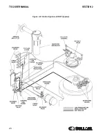
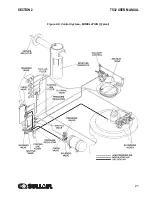
Page 20: ...TS32 USER MANUAL SECTION 2 20 Figure 2 8 Control System START Typical...
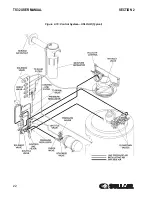
Page 21: ...SECTION 2 TS32 USER MANUAL 21 Figure 2 9 Control System MODULATION Typical...
Page 22: ...TS32 USER MANUAL SECTION 2 22 Figure 2 10 Control System UNLOAD Typical...
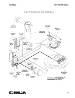
Page 23: ...SECTION 2 TS32 USER MANUAL 23 Figure 2 11 Control System FULL LOAD Typical...
Page 26: ...TS32 USER MANUAL SECTION 2 26 Figure 2 12 Compressor Air Inlet System...
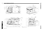
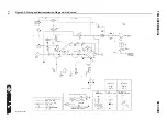
Page 30: ...TS32 USER MANUAL SECTION 3 30 Figure 3 2 Identification Air Cooled 02250126 376 R02...
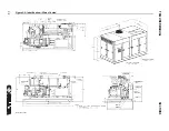
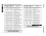
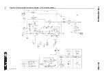
Page 32: ...TS32 USER MANUAL SECTION 3 32 Figure 3 2 Identification Water Cooled 02250126 378 R03...
Page 50: ...TS32 USER MANUAL SECTION 3 50 Figure 3 9 Wiring Diagram Air Cooled SSRV 02250178 844 R03...
Page 54: ...NOTES 54...
Page 78: ...NOTES 78...
Page 79: ...NOTES 79...

