Section 3
ES-8 MOBILE APPLICATION MANUAL R00
13
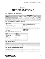
SPECIFICATIONS
3.1
TABLE OF SPECIFICATIONS
3.2
COMPRESSOR SPECIFICATIONS
3.3
MOTOR SPECIFICATIONS
3.4
FLUID FILTER
3.5
FLUID SEPARATOR ELEMENT
60 HZ
Model
HP
ACFM
PSIG
DIMENSIONS
Length
Width
Height
Weight
dBA (I)
in
mm
in
mm
in
mm
lbs
kg
w/Encls./
w/o Encls.
30XH
30
95
185
52
32
32
1065
78/85
(I)
Ratings for dBA at one meter.
COMPRESSOR:
Type:
SIngle Stage Fluid Injected Screw Compressor
Minimum Full Load Operating Pressure:
60 psig (4.2 bar)
Maximum Full Load Operating Pressure:
Nameplate Pressure
Bearing Type:
Anti-friction
Cooling:
Pressurized Fluid
Lubricant:
see
Section 3.7: Lubrication Change Recommendations &
Sump Capacity:
3 gallons (11.4 liters)
MOTOR:
60 Hz
Type:
TEFC, C-flange
Synchronous Speed:
30 HP = 3600 RPM
Voltage:
Standard All Sizes:
460
Type:
Insulation Class:
B- (Min.)
Maximum Ambient Temp.:
50ºC (122ºF)
Fluid Filter
Type:
Spin on, Sullair Proprietary
Micron:
23 Microns Abs.
Internal Bypass Valve Set at 25 psig (1.7 bar):
Fluid Separator Element
Type:
Push In Cartridge, Sullair Proprietary
Efficiency at Maximum Capacity:
5PPM Maximum
Summary of Contents for 30XH
Page 10: ...NOTES 10 ...
Page 22: ...NOTES 22 ...
Page 33: ...NOTES 33 ...
Page 34: ...INLET CONTROL SEAL DRIVE GEAR AND PARTS 34 8 3 INLET CONTROL SEAL DRIVE GEAR AND PARTS ...
Page 36: ...MOTOR COUPLING FAN AND PARTS 36 8 4 MOTOR COUPLING FAN AND PARTS ...
Page 40: ...COMPRESSOR COOLER SYSTEM AND PARTS 40 8 6 COMPRESSOR COOLER SYSTEM AND PARTS ...
Page 42: ...PNEUMATIC CONTROL SYSTEM AND PARTS 42 8 7 PNEUMATIC CONTROL SYSTEM AND PARTS ...
Page 44: ...CONTROL STARTER MFV 44 8 8 CONTROL STARTER MFV ...
Page 46: ...DECAL GROUP 46 8 9 DECAL GROUP ...
Page 48: ...DECAL GROUP 48 8 9 DECAL GROUP CONTINUED ...
Page 50: ...WIRING DIAGRAM FULL VOLTAGE STANDARD 50 8 10 WIRING DIAGRAM FULL VOLTAGE STANDARD ...
Page 51: ...NOTES 51 ...


