ES-8 MOBILE APPLICATION MANUAL R00
SECTION 2
12
2.4
COUPLING ALIGNMENT
CHECK
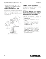
With the compressor unit directly flange-mounted to
its drive, the coupling supplied with the compressor is
always properly aligned for opertion. However, we
recommend that you re-check the coupling gap
before start-up or when handling the unit. a 1.5 to
3mm axial clearance should be maintained for the
coupling gap. See
.
2.5
FLUID LEVEL CHECK
The Sullair air compressor is equipped with the
proper amount of fluid. However, it is necessary to
check the fluid level at installation. The level is
checked by looking at the fluid level sight tube
located on the end bell. If the sump is properly filled,
the fluid level should cover 1/4 to 1/2 of the level
range during operation. With the compressor shut
down, the level should be 3/4 of the sight tube. DO
NOT overfill.
2.6
MOTOR ROTATION
DIRECTION CHECK
After the electrical wiring has been done, it is
necessary to check the direction of the motor
rotation.
Pull out the
EMERGENCY STOP
button and press
once, quickly and in succession, the
(START)
I
and
(STOP)
O
pads. This action will bump start the motor
for a very short time. When looking at the motor from
the control panel side, view the coupling by looking
through the air inlet duct on the lower side of the
adapter fan housing. The coupling should be turning
clockwise. If the reversed rotation is noted,
disconnect the power to the starter and exchange
any two of the three power input leads, then re-
check rotation. A “Direction of Rotation” decal is
located on the motor and cooler shroud to show
proper motor/compressor rotation.
2.7
ELECTRICAL PREPARATION
Interior electrical wiring is performed at the factory.
Required customer wiring is minimal, but should be
done by a qualified electrician in compliance with
OSHA, National Electrical Code, and/or any other
applicable State, Federal and local electrical codes
concerning isolation switches, fused disconnects,
etc. Sullair provides a wiring diagram for use by the
installer.
A few electrical checks should be made to help
assure that the first start-up will be trouble-free.
1. Check incoming voltage. Be sure that com-
pressor is wired for the correct incoming volt-
age.
2. Check starter for correct size, proper over-
load relay, and heaters.
3. Check all electrical connections for tight-
ness.
4. “DRY RUN” the electrical controls by discon-
necting the three (3)motor leads from the
starter. Pull out the EMERGENCY STOP
button on the control panel.
5. Reconnect the motor leads and jog the
motor for a direction of rotation check as
explained in
.
NOTE
Customer must provide electrical supply
power disconnect within sight of machine.
WARNING
Lethal shock hazard inside. Disconnect all
power at source before opening or servicing.
NOTE
Wiring diagram for standard compressors
is supplied on the inside cover of the
Control Center. Optional compressor wir-
ing diagrams will vary.
Summary of Contents for 30XH
Page 10: ...NOTES 10 ...
Page 22: ...NOTES 22 ...
Page 33: ...NOTES 33 ...
Page 34: ...INLET CONTROL SEAL DRIVE GEAR AND PARTS 34 8 3 INLET CONTROL SEAL DRIVE GEAR AND PARTS ...
Page 36: ...MOTOR COUPLING FAN AND PARTS 36 8 4 MOTOR COUPLING FAN AND PARTS ...
Page 40: ...COMPRESSOR COOLER SYSTEM AND PARTS 40 8 6 COMPRESSOR COOLER SYSTEM AND PARTS ...
Page 42: ...PNEUMATIC CONTROL SYSTEM AND PARTS 42 8 7 PNEUMATIC CONTROL SYSTEM AND PARTS ...
Page 44: ...CONTROL STARTER MFV 44 8 8 CONTROL STARTER MFV ...
Page 46: ...DECAL GROUP 46 8 9 DECAL GROUP ...
Page 48: ...DECAL GROUP 48 8 9 DECAL GROUP CONTINUED ...
Page 50: ...WIRING DIAGRAM FULL VOLTAGE STANDARD 50 8 10 WIRING DIAGRAM FULL VOLTAGE STANDARD ...
Page 51: ...NOTES 51 ...


