ES-8 MOBILE APPLICATION MANUAL R00
SECTION 3
14
3.6
LUBRICATION GUIDE
For best value and longest uninterrupted service, the
ES-8 compressor is factory filled and tested with a
long life lubricant.
Maintenance of all other components is still
recommended as indicated in the Operator’s Manual.
For light-duty high-humidity service where
condensed moisture and emulsification
(mayonnaise) may occur, the fluid change interval
must be reduced to 300 hours maximum. A non-
detergent fluid with rust, oxidation and foam
inhibitors and good water separation characteristics
should be used.
DO NOT MIX DIFFERENT TYPES OF FLUIDS.
Contamination of non-detergent mineral fluids with
traces of ATF or detergent motor fluids may lead to
operational problems such as foaming, filter
plugging, orifice or line plugging.
When ambient conditions exceed those noted or if
conditions warrant use of “extended” life lubricants
contact Sullair for recommendation.
Sullair encourages the user to participate in a fluid
analysis program. This could result in a fluid change
interval that is different from those stated in this
manual.
3.7
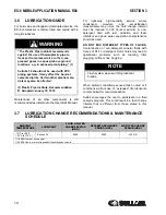
LUBRICATION CHANGE RECOMMENDATIONS & MAINTENANCE
SCHEDULE
WARNING
“The Plastic Pipe Institute recommends
against the use of thermoplastic pipe to
transport compressed air or other com-
pressed gases in exposed above ground
locations, e.g. in exposed plant piping.” (I)
Sullube 32 should not be used with PVC
piping systems. It may affect the bond at
cemented joints. Certain other plastic mate-
rials may also be affected.
(I) Plastic Pipe Institute, Recommendation
B, Adopted January 19, 1972.
NOTE
Flush system when switching lubricant
brands.
AMBIENT
TEMPERATURE
LUBRICANT
FLUID & FILTER
CHANGE PERIOD
(HRS.)
SEPARATOR CHANGES
PERIOD (HRS.)
AIR FILTER CHANGE
PERIOD (HRS.)
-10°F to +90°F
(-23°C to +32°C)
Sullube 32
8000
8000
4000 (II)
(I) 8,000 Hours or once a year
(II) 4,000 Hours or more frequently if conditions so require.
Summary of Contents for 30XH
Page 10: ...NOTES 10 ...
Page 22: ...NOTES 22 ...
Page 33: ...NOTES 33 ...
Page 34: ...INLET CONTROL SEAL DRIVE GEAR AND PARTS 34 8 3 INLET CONTROL SEAL DRIVE GEAR AND PARTS ...
Page 36: ...MOTOR COUPLING FAN AND PARTS 36 8 4 MOTOR COUPLING FAN AND PARTS ...
Page 40: ...COMPRESSOR COOLER SYSTEM AND PARTS 40 8 6 COMPRESSOR COOLER SYSTEM AND PARTS ...
Page 42: ...PNEUMATIC CONTROL SYSTEM AND PARTS 42 8 7 PNEUMATIC CONTROL SYSTEM AND PARTS ...
Page 44: ...CONTROL STARTER MFV 44 8 8 CONTROL STARTER MFV ...
Page 46: ...DECAL GROUP 46 8 9 DECAL GROUP ...
Page 48: ...DECAL GROUP 48 8 9 DECAL GROUP CONTINUED ...
Page 50: ...WIRING DIAGRAM FULL VOLTAGE STANDARD 50 8 10 WIRING DIAGRAM FULL VOLTAGE STANDARD ...
Page 51: ...NOTES 51 ...


