ES-8 MOBILE APPLICATION MANUAL R00
SECTION 5
20
5.3
LCD DISPLAY
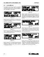
The display's normal view shows the compressor
package's discharge pressure, internal temperature,
and the operating mode. The modes are MANUAL,
OFF, AUTOMATIC, or FAULTED.
Figure 5-2:
Refer to
and
. The lower line is
occasionally interrupted to describe the compressor
package's operating state.
Figure 5-3:
. If a machine fault occurs, the red
fault " " indicator will light up, and the display will
indicate that a fault has occurred.
Figure 5-4:
. The lower line periodically will
display the cause of the fault. Refer to service
instructions to correct the cause. Press the Stop pad
" " to reset the controller.
Figure 5-5:
. Press the Down arrow " " to
display additional information about the compressor.
The upper line will indicate "Compressor Status" and
the name of the temperature, pressure, or other
measurement. The lower line indicates the present
reading.
Figure 5-6:
. When you continue beyond the
status information, the display will show a list of
control settings. The upper line will indicate "Show
Setting" and the name of the setting. The lower line
shows the present value.
Figure 5-7:
. To change the setting, press the
Enter pad " ". The display indicates that you are in a
change mode with reverse characters. Use the Up " "
or Down " " arrow keys to change the setting, and
press Enter again to save the new setting.
Summary of Contents for 30XH
Page 10: ...NOTES 10 ...
Page 22: ...NOTES 22 ...
Page 33: ...NOTES 33 ...
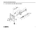
Page 34: ...INLET CONTROL SEAL DRIVE GEAR AND PARTS 34 8 3 INLET CONTROL SEAL DRIVE GEAR AND PARTS ...
Page 36: ...MOTOR COUPLING FAN AND PARTS 36 8 4 MOTOR COUPLING FAN AND PARTS ...
Page 40: ...COMPRESSOR COOLER SYSTEM AND PARTS 40 8 6 COMPRESSOR COOLER SYSTEM AND PARTS ...
Page 42: ...PNEUMATIC CONTROL SYSTEM AND PARTS 42 8 7 PNEUMATIC CONTROL SYSTEM AND PARTS ...
Page 44: ...CONTROL STARTER MFV 44 8 8 CONTROL STARTER MFV ...
Page 46: ...DECAL GROUP 46 8 9 DECAL GROUP ...
Page 48: ...DECAL GROUP 48 8 9 DECAL GROUP CONTINUED ...
Page 50: ...WIRING DIAGRAM FULL VOLTAGE STANDARD 50 8 10 WIRING DIAGRAM FULL VOLTAGE STANDARD ...
Page 51: ...NOTES 51 ...

