ES-8 MOBILE APPLICATION MANUAL R00
SECTION 6
24
6.5
COOLER MAINTENANCE
If cooler becomes restricted, use standard spray
degreaser/cleaner and brush to clean cooler. Use air
pressure to blow cooler clean. Care must be taken as
not to damage cooler fins.
6.6
PARTS REPLACEMENT AND
ADJUSTMENT
PROCEDURES
RELIEF VALVE
DO NOT
tamper with the preset factory pressure
setting of the valve.
DO NOT
plug the valve for any
reason; should it leak, have it replaced.
FLUID FILTER REPLACEMENT
Refer to
1. To prevent spillage and loss of reusable fluid,
place a contaminate-free fluid receptacle beneath
fluid drain valve and fluid filter.
2. Drain fluid by removing fluid drain valve cap at tee
located beneath compressor (for complete fluid
change, drain fluid from cooler).
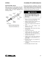
3. Using a strap wrench, remove the old element and
gasket.
4. Clean gasket seating surface.
5. Apply a light film of fluid to the new gasket.
6. Hand tighten new element until gasket is seated.
7. Continue tightening element an additional 1/2 to
3/4 turn.
8. Replace fluid. DO NOT OVERFILL.
9. Restart compressor and check for leaks.
WARNING
Before doing compressor maintenance, dis-
connect compressor from power source
and lock out power source. Isolate com-
pressor from line pressure by closing rec-
ommended discharge shut-off valve and
releasing all internal pressure from com-
pressor.
WARNING
Before doing compressor maintenance, dis-
connect compressor from power source
and lock out power source. Isolate com-
pressor from line pressure by closing rec-
ommended discharge shut-off valve and
releasing all internal pressure from com-
pressor.
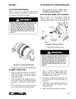
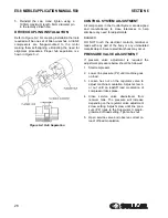
Figure 6-1: Fluid Filter (P/N 250026--982)
* Replacement Element Kit P/N 02250050--602
Summary of Contents for 30XH
Page 10: ...NOTES 10 ...
Page 22: ...NOTES 22 ...
Page 33: ...NOTES 33 ...
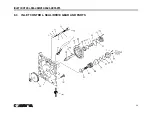
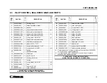
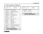
Page 34: ...INLET CONTROL SEAL DRIVE GEAR AND PARTS 34 8 3 INLET CONTROL SEAL DRIVE GEAR AND PARTS ...
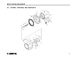
Page 36: ...MOTOR COUPLING FAN AND PARTS 36 8 4 MOTOR COUPLING FAN AND PARTS ...
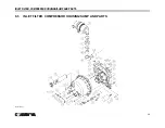
Page 40: ...COMPRESSOR COOLER SYSTEM AND PARTS 40 8 6 COMPRESSOR COOLER SYSTEM AND PARTS ...
Page 42: ...PNEUMATIC CONTROL SYSTEM AND PARTS 42 8 7 PNEUMATIC CONTROL SYSTEM AND PARTS ...
Page 44: ...CONTROL STARTER MFV 44 8 8 CONTROL STARTER MFV ...
Page 46: ...DECAL GROUP 46 8 9 DECAL GROUP ...
Page 48: ...DECAL GROUP 48 8 9 DECAL GROUP CONTINUED ...
Page 50: ...WIRING DIAGRAM FULL VOLTAGE STANDARD 50 8 10 WIRING DIAGRAM FULL VOLTAGE STANDARD ...
Page 51: ...NOTES 51 ...

