Section 7
ES-8 MOBILE APPLICATION MANUAL R00
29
TROUBLESHOOTING
7.1
INTRODUCTION
The information contained in the Troubleshooting
chart is based upon both the actual applied situations
and extensive testing at the factory. It contains
symptoms and usual causes for the described
problems. However DO NOT assume that these are
the only problems that may occur. All available data
concerning the trouble should be systematically
analyzed before undertaking any repair or
component replacement procedures.
A detailed visual inspection is worth performing for
almost any problems which may prevent
unnecessary damage to the compressor. Always
remember to:
a.
Check for loose wiring.
b.
Check for damaged piping.
c.
Check for parts damaged by heat or an elec-
trical short circuit, usually apparent by discol-
oration or a burnt odor.
Should your problem persist after making the
recommended check, consult your nearest Sullair
representative or the Sullair Corporation factory.
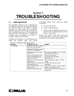
Table 7-1: Controller Troubleshooting Guide
MESSAGE
PROBABLE CAUSE
REMEDY
T1 HI Message
Discharge Temperature Exceeded
225°F (107°C) for Pre-Alarm
Discharge Temperature Exceeded
235°F (113°C) for Shutdown
Ambient temperature exceeded
105°F (41°C)
Improve local ventilation (i.e., remote intake
of process and/or cooling air.
Fluid Level in Sump is Too Low
Check/correct fluid level.
Thermal Valve Malfunctioned
Check/replace thermal valve.
Cooler Fins are Dirty
Clean cooler fins.
Water Flow is Low (water--cooled
packages only)
Check cooling water supply (i.e., closed
valves).
Water Temperature is High (water-
cooled packages only)
Increase water flow, lower water
temperature.
Cooler is Plugged (water--cooled
packages only)
Clean tubes and/or shell -- if tube plugging
persists, provide cleaner water.
Temperature RTD Malfunction
Check connections from RTD. If adequate,
replace RTD.
Summary of Contents for 30XH
Page 10: ...NOTES 10 ...
Page 22: ...NOTES 22 ...
Page 33: ...NOTES 33 ...
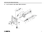
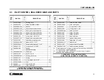
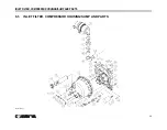
Page 34: ...INLET CONTROL SEAL DRIVE GEAR AND PARTS 34 8 3 INLET CONTROL SEAL DRIVE GEAR AND PARTS ...
Page 36: ...MOTOR COUPLING FAN AND PARTS 36 8 4 MOTOR COUPLING FAN AND PARTS ...
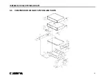
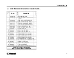
Page 40: ...COMPRESSOR COOLER SYSTEM AND PARTS 40 8 6 COMPRESSOR COOLER SYSTEM AND PARTS ...
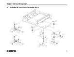
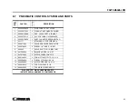
Page 42: ...PNEUMATIC CONTROL SYSTEM AND PARTS 42 8 7 PNEUMATIC CONTROL SYSTEM AND PARTS ...
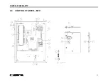
Page 44: ...CONTROL STARTER MFV 44 8 8 CONTROL STARTER MFV ...
Page 46: ...DECAL GROUP 46 8 9 DECAL GROUP ...
Page 48: ...DECAL GROUP 48 8 9 DECAL GROUP CONTINUED ...
Page 50: ...WIRING DIAGRAM FULL VOLTAGE STANDARD 50 8 10 WIRING DIAGRAM FULL VOLTAGE STANDARD ...
Page 51: ...NOTES 51 ...

