PARTS MANUAL R00
31
8.1
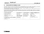
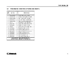
PROCEDURE FOR ORDERING PARTS
Parts should be ordered from the nearest Sullair Representative or the Representative from whom the compressor was purchased. If for any reason
parts cannot be obtained in this manner, contact the factory directly at the address, phone numbers or fax numbers below.
When ordering parts always indicate the Serial Number of the compressor. This can be obtained from the Bill of Lading for the compressor unit or
from the Serial Number Plate located on the compressor unit.
The genuine Sullair service parts listed meet or exceed the demands of this compressor. Use of replacement parts other than those approved by
Sullair Corporation may lead to hazardous conditions over which Sullair Corporation has no control. Such conditions include, but are not limited to,
bodily injury and compressor failure.
SULLAIR CORPORATION
3700 East Michigan Boulevard
Michigan City, Indiana 46360 U.S.A
www.sullair.com
Telephone: 1-800-SULLAIR (U.S.A. only)
Fax: 219-874-1273
CUSTOMER CARE for PARTS and SERVICE
1-888-SULLAIR (785-5247)
219-874-1835
SULLAIR ASIA, LTD.
Sullair Road, No. 1
Chiwan, Shekuo
Shenzhen, Guangdong PRV.
PRC POST CODE 518068
Telephone: 755-6851686
Fax: 755-6853473
www.sullair-asia.com
SULLAIR EUROPE, S.A.
Zone Des Granges BP 82
42602 Montbrison, France
Telephone: 33-477968470
Fax: 33-477968499
www.sullaireurope.com
CHAMPION COMPRESSORS, LTD.
Princess Highway
Hallam, Victoria 3803
Austrailia
Telephone: 61-3-9796-4000
Fax: 61-3-9703-8053
www.championcompressors.com.au
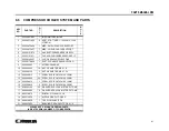
PARTS LIST
Section 9
Summary of Contents for 30XH
Page 10: ...NOTES 10 ...
Page 22: ...NOTES 22 ...
Page 33: ...NOTES 33 ...
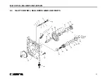
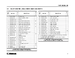
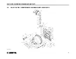
Page 34: ...INLET CONTROL SEAL DRIVE GEAR AND PARTS 34 8 3 INLET CONTROL SEAL DRIVE GEAR AND PARTS ...
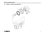
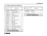
Page 36: ...MOTOR COUPLING FAN AND PARTS 36 8 4 MOTOR COUPLING FAN AND PARTS ...
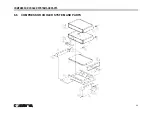
Page 40: ...COMPRESSOR COOLER SYSTEM AND PARTS 40 8 6 COMPRESSOR COOLER SYSTEM AND PARTS ...
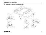
Page 42: ...PNEUMATIC CONTROL SYSTEM AND PARTS 42 8 7 PNEUMATIC CONTROL SYSTEM AND PARTS ...
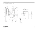
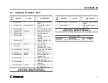
Page 44: ...CONTROL STARTER MFV 44 8 8 CONTROL STARTER MFV ...
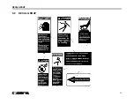
Page 46: ...DECAL GROUP 46 8 9 DECAL GROUP ...
Page 48: ...DECAL GROUP 48 8 9 DECAL GROUP CONTINUED ...
Page 50: ...WIRING DIAGRAM FULL VOLTAGE STANDARD 50 8 10 WIRING DIAGRAM FULL VOLTAGE STANDARD ...
Page 51: ...NOTES 51 ...

