19
oPERATIon
7
6
4
3
2
1
5
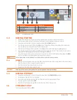
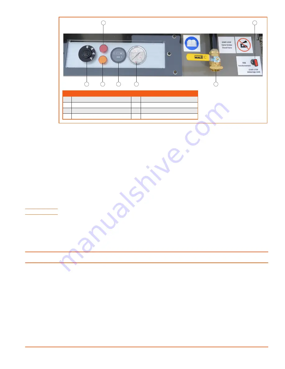
Figure 5-1.
D110PKU INSTRUMENT PANEL
5.3
NORMAL STARTING
1.
Inspect the compressor, engine, and other assemblies for damage or loose connections.
2.
Check engine water, oil, fuel, and battery fluid levels. Check compressor receiver oil level.
3.
Close Service Valve (
2
). Turn Start-Stop/Run Valve (
1
) to
START
position.
4.
Turn the Key Ignition Switch (
7
) to the
ON
postion. The Battery Charge Lamp (
5
) will then illuminate.
Security devices are stopped during the starting process.
5.
Preheating. Hold Key Ignition Switch (
7
) in the
GL
postion until Preheating Lamp (
6
) goes out.
6.
Turn the Key Ignition Switch (
7
) to the
ST
position to engage the starter. Then release as soon as the
engine starts. (Glow plug preheating occurs during this phase.)
7.
Allow the compressor to warm up for about 5 minutes. Turn the Start-Stop/Run Valve (
1
) to the
RUN
position to obtain a stabilized pressure between 90 to 100 psi.
NOTE!
If the engine stops, do not attempt to restart with the oil receiver under pressure.
5.4
USAGE
1.
Check that the compressor Service Valve (
2
) is closed and connect the supply hose to the valve. Slowly
open the Service Valve to purge any water present.
2.
Shut the valve before connecting to any tools.
3.
Slowly open the valve when ready for use.
WARNING!
Never open the service valve quickly. Pressurize equipment slowly and safely.
5.5
NORMAL STOPPING
1.
Close Service Valve (
2
). Turn Start-Stop/Run Valve (
1
) to the
START-STOP
position.
2.
Run engine at low idle for 1 to 2 minutes
.
3.
open and close the Service
V
alve (
2
)
to reduce pressure to approximately 70 psi.
4.
Turn Key Ignition Switch (
7
) to
OFF
.
5.
Check that the Pressure Gauge (
3
) is reduced to 0 psi after a few seconds.
5.6
EMERGENCY STOP
Turn Key Ignition Switch (
7
) to
OFF.
#
COMPONENT
#
COMPONENT
1
Start-Stop/Run Valve
5
Battery Charge Lamp
2
Service Valve
6
Preheating Lamp
3
Pressure Gauge
7
Key Ignition Switch
4
Hourmeter
Summary of Contents for D110PKU
Page 4: ......
Page 6: ...vi About This Manual ...
Page 13: ...5 2 SPECIFICATIONS TOPICS IN THIS SECTION Technical Data 6 Dimensions 7 ...
Page 16: ...8 Specifications ...
Page 44: ...36 Troubleshooting ...
Page 48: ...40 Parts Catalog 8 6 ENGINE ASSEMBLY ...
Page 50: ...42 Parts Catalog 8 7 ENGINE MOUNTING ASSEMBLY ...
Page 52: ...44 Parts Catalog 8 8 ENGINE TO FRAME ASSEMBLY ...
Page 54: ...46 Parts Catalog 8 9 BATTERY ASSEMBLY ...
Page 56: ...48 Parts Catalog 8 10 EXHAUST ASSEMBLY ...
Page 58: ...50 Parts Catalog 8 11 COMPRESSOR ASSEMBLY ...
Page 60: ...52 Parts Catalog 8 12 INLET VALVE ASSEMBLY ...
Page 62: ...54 Parts Catalog 8 13 AIR FILTER ASSEMBLY ...
Page 64: ...56 Parts Catalog 8 14 RECEIVER ASSEMBLY ...
Page 66: ...58 Parts Catalog 8 15 RECEIVER ASSEMBLY TO FRAME ...
Page 68: ...60 Parts Catalog 8 16 CONTROL TUBING ASSEMBLY ...
Page 70: ...62 Parts Catalog 8 17 COOLING ASSEMBLY ...
Page 72: ...64 Parts Catalog 8 18 COOLING ASSEMBLY ATTACHMENT TO FRAME ...
Page 74: ...66 Parts Catalog 8 19 COOLING SYSTEM HOSES AND RECOVERY TANK INSTALLATION ...
Page 76: ...68 Parts Catalog 8 20 OIL FILTER AND DISCHARGE HOSE ASSEMBLY ...
Page 78: ...70 Parts Catalog 8 21 FUEL TANK ASSEMBLY ...
Page 80: ...72 Parts Catalog 8 22 INSTRUMENT PANEL ASSEMBLY ...
Page 82: ...74 Parts Catalog 8 23 CANOPY ASSEMBLY ...
Page 84: ...76 Parts Catalog 8 24 CANOPY INSTALLATION ...
Page 86: ...78 Parts Catalog 8 25 LIFTING BAIL ASSEMBLY ...
Page 88: ...80 Parts Catalog 8 26 FRONT CROSSMEMBER ASSEMBLY ...
Page 90: ...82 Parts Catalog 8 27 LIGHT PACKAGE ...
Page 92: ...84 Parts Catalog 8 28 FENDER INSTALLATION ...
Page 94: ...86 Parts Catalog 8 29 AXLE AND WHEEL ASSEMBLY ...
Page 98: ...NOTES ...
Page 99: ...NOTES ...


