24
MAINTENANCE
6.1
MAINTENANCE
The maintenance procedures indicated in this manual are given for normal conditions of use. In difficult
conditions, temperatures extremes, high hygrometry, atmospheric pollution, high elevation, etc. some
maintenance must be performed more frequently and particular precautions must be taken.
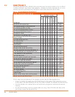
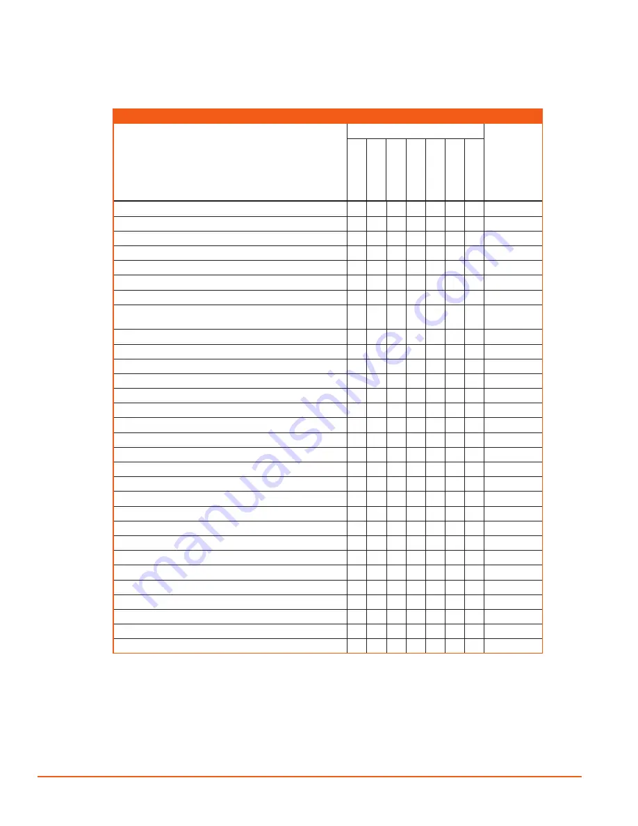
6.1.1 MAINTENANCE SCHEDULE
D110PKU RECOMMENDED MAINTENANCE
PROCEDURE
FREQUENCY (HOURS)
REFERENCE
D
A
ILY
50
10
0
20
0
400
60
0 o
r y
ea
rly
12
00 o
r 2 y
rs
Check oil level (before starting)
x
6.3.1
Check radiator coolant level (before starting)
x
6.8
Check fuel supply (before starting)
x
Check air filter elements (before starting)
x
6.7
Check fuel pre-filter (before starting)
x
Check battery charge
x
x
Check for fuel, oil air and water leaks
x
Check compressor drive belt and fan belt tension
(before starting)
x
x
6.11
Purge the fuel tank and circuit
x
Check fuel pre-filter
x
Check bolt torque
x
Drain the sump
x
Change the oil filter element
x
x
x
6.5
Change fuel filter element and pre-filter
x
x
Check the control functioning (speed and pressure)
x
Clean engine radiator and compressor cooler core
x
6.8
Clean separator dip tube mesh strainer
x
6.6
Lubricate hinge points
x
Check tire pressure and tightness of wheel nuts
x
Change air filter element (or as needed)
x
6.7
Check cooler hoses and hose clamps
x
6.8
Change separator oil and element (or as needed)
x
6.6
Change compressor drive belt and fan belt
x
6.11
Check max. speed and idle speed
x
Change radiator coolant
x
6.8
Check valve clearance
x
Check regulating system
x
Clean fuel tank
x
Replace fuel and lubricant ducts and fixing clamps
x
Replace cooler hoses and hose clamps
x
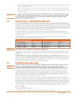
Prior to inspection or maintenance of the compressor always take the following precautions:
»
Ensure it is located on a large level surface. Do NOT work on compressor if ONLY placed on a jack or a
winch. Always use adapted wheel chocks or safety stands to support the compressor before servicing.
»
Stop the compressor and remove the key before performing any periodic maintenance checks and
cleaning.
»
Disconnect the battery from the compressor before servicing. Place a “DO NOT USE!” label on the
ignition key to prevent accidental starting.
Summary of Contents for D110PKU
Page 4: ......
Page 6: ...vi About This Manual ...
Page 13: ...5 2 SPECIFICATIONS TOPICS IN THIS SECTION Technical Data 6 Dimensions 7 ...
Page 16: ...8 Specifications ...
Page 44: ...36 Troubleshooting ...
Page 48: ...40 Parts Catalog 8 6 ENGINE ASSEMBLY ...
Page 50: ...42 Parts Catalog 8 7 ENGINE MOUNTING ASSEMBLY ...
Page 52: ...44 Parts Catalog 8 8 ENGINE TO FRAME ASSEMBLY ...
Page 54: ...46 Parts Catalog 8 9 BATTERY ASSEMBLY ...
Page 56: ...48 Parts Catalog 8 10 EXHAUST ASSEMBLY ...
Page 58: ...50 Parts Catalog 8 11 COMPRESSOR ASSEMBLY ...
Page 60: ...52 Parts Catalog 8 12 INLET VALVE ASSEMBLY ...
Page 62: ...54 Parts Catalog 8 13 AIR FILTER ASSEMBLY ...
Page 64: ...56 Parts Catalog 8 14 RECEIVER ASSEMBLY ...
Page 66: ...58 Parts Catalog 8 15 RECEIVER ASSEMBLY TO FRAME ...
Page 68: ...60 Parts Catalog 8 16 CONTROL TUBING ASSEMBLY ...
Page 70: ...62 Parts Catalog 8 17 COOLING ASSEMBLY ...
Page 72: ...64 Parts Catalog 8 18 COOLING ASSEMBLY ATTACHMENT TO FRAME ...
Page 74: ...66 Parts Catalog 8 19 COOLING SYSTEM HOSES AND RECOVERY TANK INSTALLATION ...
Page 76: ...68 Parts Catalog 8 20 OIL FILTER AND DISCHARGE HOSE ASSEMBLY ...
Page 78: ...70 Parts Catalog 8 21 FUEL TANK ASSEMBLY ...
Page 80: ...72 Parts Catalog 8 22 INSTRUMENT PANEL ASSEMBLY ...
Page 82: ...74 Parts Catalog 8 23 CANOPY ASSEMBLY ...
Page 84: ...76 Parts Catalog 8 24 CANOPY INSTALLATION ...
Page 86: ...78 Parts Catalog 8 25 LIFTING BAIL ASSEMBLY ...
Page 88: ...80 Parts Catalog 8 26 FRONT CROSSMEMBER ASSEMBLY ...
Page 90: ...82 Parts Catalog 8 27 LIGHT PACKAGE ...
Page 92: ...84 Parts Catalog 8 28 FENDER INSTALLATION ...
Page 94: ...86 Parts Catalog 8 29 AXLE AND WHEEL ASSEMBLY ...
Page 98: ...NOTES ...
Page 99: ...NOTES ...

