10
COMPONENT DESCRIPTION
3.1
COMPRESSOR PACKAGE
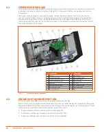
This package includes a diesel KUboTA 3-cylinder engine (type D1105), an air end, a capacity control system,
a compressor cooling system and a battery. Please refer to engine and battery usage manuals for more
information.
The engine cooling system is comprised of a water radiator and an oil radiator for the air end. The fan,
which is common to both radiators, is used to exhaust air and to maintain both engine and air end at the
appropriate running temperature. The engine drives the air end via trapezoidal belts. The compressor’s
fuel tank has sufficient capacity for a full day’s operation. The compressor includes safety devices for both
running temperature and pressure.
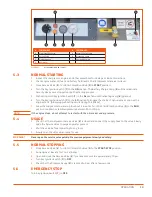
Figure 3-1.
D110PKU COMPRESSOR COMPONENTS
3.2
ENGINE SHUTDOWN PROTECTION
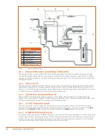
The Safety Relief Valve (
15
) is located on the Separator/Receiver Tank (
6
).
When a fault occurs the engine will shut down when one of three safety devices are triggered by the Engine
Stop Solenoid (
14
). The battery charge lamp on the instrument panel then lights up to indicate a fault. These
safety devices protect the engine and compressor against the risk of:
1.
Engine oil pressure drop: pressure switch on the Engine (
1
)
2.
Compressor overheating: temperature switch on the Air End (
7
)
3.
Engine overheating: water temperature switch on the Engine (
1
)
#
COMPONENT
#
COMPONENT
1
Engine
9
Engine Oil Fill
2
Compressor Oil Filter
10
Engine Speed Cylinder
3
Air Filter compressor / motor
11
Engine Oil Dipstick
4
Cooler compressor / motor
12
Engine Oil Filter
5
Inlet Valve
13
Fuel Filter
6
Separator / Receiver Tank
14
Engine Stop Solenoid
7
Compressor / Air End
15
Safety Relief Valve
8
Compressor Oil Fill
16
Fan
Summary of Contents for D110PKU
Page 4: ......
Page 6: ...vi About This Manual ...
Page 13: ...5 2 SPECIFICATIONS TOPICS IN THIS SECTION Technical Data 6 Dimensions 7 ...
Page 16: ...8 Specifications ...
Page 44: ...36 Troubleshooting ...
Page 48: ...40 Parts Catalog 8 6 ENGINE ASSEMBLY ...
Page 50: ...42 Parts Catalog 8 7 ENGINE MOUNTING ASSEMBLY ...
Page 52: ...44 Parts Catalog 8 8 ENGINE TO FRAME ASSEMBLY ...
Page 54: ...46 Parts Catalog 8 9 BATTERY ASSEMBLY ...
Page 56: ...48 Parts Catalog 8 10 EXHAUST ASSEMBLY ...
Page 58: ...50 Parts Catalog 8 11 COMPRESSOR ASSEMBLY ...
Page 60: ...52 Parts Catalog 8 12 INLET VALVE ASSEMBLY ...
Page 62: ...54 Parts Catalog 8 13 AIR FILTER ASSEMBLY ...
Page 64: ...56 Parts Catalog 8 14 RECEIVER ASSEMBLY ...
Page 66: ...58 Parts Catalog 8 15 RECEIVER ASSEMBLY TO FRAME ...
Page 68: ...60 Parts Catalog 8 16 CONTROL TUBING ASSEMBLY ...
Page 70: ...62 Parts Catalog 8 17 COOLING ASSEMBLY ...
Page 72: ...64 Parts Catalog 8 18 COOLING ASSEMBLY ATTACHMENT TO FRAME ...
Page 74: ...66 Parts Catalog 8 19 COOLING SYSTEM HOSES AND RECOVERY TANK INSTALLATION ...
Page 76: ...68 Parts Catalog 8 20 OIL FILTER AND DISCHARGE HOSE ASSEMBLY ...
Page 78: ...70 Parts Catalog 8 21 FUEL TANK ASSEMBLY ...
Page 80: ...72 Parts Catalog 8 22 INSTRUMENT PANEL ASSEMBLY ...
Page 82: ...74 Parts Catalog 8 23 CANOPY ASSEMBLY ...
Page 84: ...76 Parts Catalog 8 24 CANOPY INSTALLATION ...
Page 86: ...78 Parts Catalog 8 25 LIFTING BAIL ASSEMBLY ...
Page 88: ...80 Parts Catalog 8 26 FRONT CROSSMEMBER ASSEMBLY ...
Page 90: ...82 Parts Catalog 8 27 LIGHT PACKAGE ...
Page 92: ...84 Parts Catalog 8 28 FENDER INSTALLATION ...
Page 94: ...86 Parts Catalog 8 29 AXLE AND WHEEL ASSEMBLY ...
Page 98: ...NOTES ...
Page 99: ...NOTES ...


