16
TRANSPORTING AND LOCATING
»
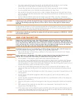
Do not exceed maximum towing speeds. Reduce speed accordingly, as dictated by posted signs, weather,
road, or terrain conditions.
»
Remember that portable air compressors may approach or exceed the weight of the towing vehicle.
Maintain increased stopping distance accordingly.
»
Grades in excess of 15° (27%) or any grade that would over-extend the towing or braking ability of the
towing vehicle should be avoided.
»
When towing the compressor, avoid potholes, rocks, rough terrain, obstructions and soft shoulders.
Damage to the undercarriage and suspension can result.
»
Do not permit any person to ride in or on the compressor while being towed. Serious injury can result.
»
Make sure the area behind and under the compressor is clear of all persons, animals and obstructions
prior to backing.
»
Do not permit anyone to stand or ride on the drawbar, or to stand or walk between the compressor and
the towing vehicle. Serious injury or death can result.
4.5.1 MAXIMUM RECOMMENDED TOWING SPEED ON SMOOTH, DRY ROADS
Single and two axle compressors:
. . . . . . . . . . . . . . . . . . . . . . . . . . . . . . . . . . . . . . . . . . . . . . . . . . . . .
55mph (89kmh)
WARNING!
Failure to comply with maximum towing speed may cause property damage and serious bodily injury
or death.
4.6
PARKING OR LOCATING COMPRESSOR
»
Park or locate compressor on level ground or across grade.
»
Make sure compressor is parked or located on a firm surface that can support its weight.
»
Park or locate compressor to cause the prevailing wind to direct the exhaust fumes and radiator heat
away from the compressor air inlet openings and to prevent ingestion of dust and debris from the work
site.
»
Set parking brakes and disconnect breakaway switch cable and all other interconnecting electrical and
break connections, if provided.
»
Block or chock both sides of all wheels.
»
Block or chock both sides of drawbar stabilizer leg or jack.
»
Unhook chains and remove them from the points of attachment on the towing vehicle, then hook chains
to each other on drawbar or wrap chains around the drawbar in order to keep them off the ground.
»
If provided, lower front screw jack and rear stabilizer legs. Make sure the ground is firm and capable of
supporting the weight of the compressor.
»
If the compressor is provided with a swivel caster wheel, pull pin and lower caster wheel, then make sure
pin is re-engaged to secure caster wheel in the full-down and locked position.
»
Disconnect coupling device, keeping hands and fingers clear of all pinch points. Do not attempt to lift
the drawbar of portable compressors by hand if the weight is more than you can safely handle - usually
weights in excess of 50 pounds. Use a lifting device such as a jack or chain hoist to lift the drawbar to
avoid injury to yourself or others.
»
Keep feet clear of drawbar at all times to avoid crushing accidents in case it should slip from your hands
or otherwise fall to the ground.
NOTE!
These guidelines also apply for locating and securing non-towed compressors (skid mounted and utility
models). Obviously, reference to towing may not apply.
Summary of Contents for D110PKU
Page 4: ......
Page 6: ...vi About This Manual ...
Page 13: ...5 2 SPECIFICATIONS TOPICS IN THIS SECTION Technical Data 6 Dimensions 7 ...
Page 16: ...8 Specifications ...
Page 44: ...36 Troubleshooting ...
Page 48: ...40 Parts Catalog 8 6 ENGINE ASSEMBLY ...
Page 50: ...42 Parts Catalog 8 7 ENGINE MOUNTING ASSEMBLY ...
Page 52: ...44 Parts Catalog 8 8 ENGINE TO FRAME ASSEMBLY ...
Page 54: ...46 Parts Catalog 8 9 BATTERY ASSEMBLY ...
Page 56: ...48 Parts Catalog 8 10 EXHAUST ASSEMBLY ...
Page 58: ...50 Parts Catalog 8 11 COMPRESSOR ASSEMBLY ...
Page 60: ...52 Parts Catalog 8 12 INLET VALVE ASSEMBLY ...
Page 62: ...54 Parts Catalog 8 13 AIR FILTER ASSEMBLY ...
Page 64: ...56 Parts Catalog 8 14 RECEIVER ASSEMBLY ...
Page 66: ...58 Parts Catalog 8 15 RECEIVER ASSEMBLY TO FRAME ...
Page 68: ...60 Parts Catalog 8 16 CONTROL TUBING ASSEMBLY ...
Page 70: ...62 Parts Catalog 8 17 COOLING ASSEMBLY ...
Page 72: ...64 Parts Catalog 8 18 COOLING ASSEMBLY ATTACHMENT TO FRAME ...
Page 74: ...66 Parts Catalog 8 19 COOLING SYSTEM HOSES AND RECOVERY TANK INSTALLATION ...
Page 76: ...68 Parts Catalog 8 20 OIL FILTER AND DISCHARGE HOSE ASSEMBLY ...
Page 78: ...70 Parts Catalog 8 21 FUEL TANK ASSEMBLY ...
Page 80: ...72 Parts Catalog 8 22 INSTRUMENT PANEL ASSEMBLY ...
Page 82: ...74 Parts Catalog 8 23 CANOPY ASSEMBLY ...
Page 84: ...76 Parts Catalog 8 24 CANOPY INSTALLATION ...
Page 86: ...78 Parts Catalog 8 25 LIFTING BAIL ASSEMBLY ...
Page 88: ...80 Parts Catalog 8 26 FRONT CROSSMEMBER ASSEMBLY ...
Page 90: ...82 Parts Catalog 8 27 LIGHT PACKAGE ...
Page 92: ...84 Parts Catalog 8 28 FENDER INSTALLATION ...
Page 94: ...86 Parts Catalog 8 29 AXLE AND WHEEL ASSEMBLY ...
Page 98: ...NOTES ...
Page 99: ...NOTES ...


