18
oPERATIon
5.1
GENERAL OPERATING SAFETY
»
Allow at least ten feet of unobstructed area in front of cooling air inlets and outlets to ensure good
airflow.
»
Do not start the engine by shorting the starter connections
–the compressor could start and run.
»
Do not wear headphones to listen to music or the radio when operating the compressor.
»
If compressor is connected to a common header with one or more compressors, a check valve must be
provided between each compressor and header.
»
Check instruments periodically during operation. If readings are abnormal, refer to
»
Make sure that the correct type and viscosity of lubricating oils and fuel are used, especially in extreme
ambient temperatures.
»
Replace any faulty gauge immediately.
»
Keep batteries fully charged and properly maintained.
»
Keep control linkage clean and lightly lubricated.
5.2
PREPARING FOR INITIAL START-UP
1.
Inspect the compressor, engine, and other assemblies for damage or loose connections which might
have occurred during shipment. Detect and repair leaks immediately.
2.
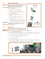
Check the engine’s crankcase oil level. If required, add oil as recommended in the Engine Manual.
3.
Check the radiator coolant level. Also, if the machine will be exposed to sub-freezing temperatures,
check the specific gravity to ascertain the freezing point of the coolant.
be sure to tighten the radiator
pressure cap securely after filling up.
4.
Fill the fuel tank with fuel recommended in the Engine Manual. Do not use unapproved containers, e.g.
buckets, bottles, or jars. Use fuel storage containers and approved dispensers.
WARNING!
Never add gasoline to diesel fuel tank - serious damage to the engine will result.
5.
If necessary, add lubricating oil to the compressor sump. Refer to
6.3 Compressor Lubrication on page
for lubricating oil specifications.
6.
Check battery posts and cable clamps to ensure proper contact. Connect positive cable and negative
cable battery terminals.
Turn ignition circuit breaker to
ON
position. Check gauge panel alternator light.
If connections are secure light will be on. If not, the battery may need an initial charge to activate it.
Check compressor air filter cleanliness if working in a very dusty environment. Pinch dust valve drain.
7.
Make sure the separator pressure is 0.
8.
During cold days, always follow the instructions given in the engine manual.
9.
Check the separator oil level to make sure that it is at maximum oil level. The maximum level is
determined by the filling hole and cannot be overfilled.
Summary of Contents for D110PKU
Page 4: ......
Page 6: ...vi About This Manual ...
Page 13: ...5 2 SPECIFICATIONS TOPICS IN THIS SECTION Technical Data 6 Dimensions 7 ...
Page 16: ...8 Specifications ...
Page 44: ...36 Troubleshooting ...
Page 48: ...40 Parts Catalog 8 6 ENGINE ASSEMBLY ...
Page 50: ...42 Parts Catalog 8 7 ENGINE MOUNTING ASSEMBLY ...
Page 52: ...44 Parts Catalog 8 8 ENGINE TO FRAME ASSEMBLY ...
Page 54: ...46 Parts Catalog 8 9 BATTERY ASSEMBLY ...
Page 56: ...48 Parts Catalog 8 10 EXHAUST ASSEMBLY ...
Page 58: ...50 Parts Catalog 8 11 COMPRESSOR ASSEMBLY ...
Page 60: ...52 Parts Catalog 8 12 INLET VALVE ASSEMBLY ...
Page 62: ...54 Parts Catalog 8 13 AIR FILTER ASSEMBLY ...
Page 64: ...56 Parts Catalog 8 14 RECEIVER ASSEMBLY ...
Page 66: ...58 Parts Catalog 8 15 RECEIVER ASSEMBLY TO FRAME ...
Page 68: ...60 Parts Catalog 8 16 CONTROL TUBING ASSEMBLY ...
Page 70: ...62 Parts Catalog 8 17 COOLING ASSEMBLY ...
Page 72: ...64 Parts Catalog 8 18 COOLING ASSEMBLY ATTACHMENT TO FRAME ...
Page 74: ...66 Parts Catalog 8 19 COOLING SYSTEM HOSES AND RECOVERY TANK INSTALLATION ...
Page 76: ...68 Parts Catalog 8 20 OIL FILTER AND DISCHARGE HOSE ASSEMBLY ...
Page 78: ...70 Parts Catalog 8 21 FUEL TANK ASSEMBLY ...
Page 80: ...72 Parts Catalog 8 22 INSTRUMENT PANEL ASSEMBLY ...
Page 82: ...74 Parts Catalog 8 23 CANOPY ASSEMBLY ...
Page 84: ...76 Parts Catalog 8 24 CANOPY INSTALLATION ...
Page 86: ...78 Parts Catalog 8 25 LIFTING BAIL ASSEMBLY ...
Page 88: ...80 Parts Catalog 8 26 FRONT CROSSMEMBER ASSEMBLY ...
Page 90: ...82 Parts Catalog 8 27 LIGHT PACKAGE ...
Page 92: ...84 Parts Catalog 8 28 FENDER INSTALLATION ...
Page 94: ...86 Parts Catalog 8 29 AXLE AND WHEEL ASSEMBLY ...
Page 98: ...NOTES ...
Page 99: ...NOTES ...


