27
MAINTENANCE
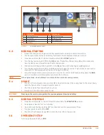
SUbMIT OIL SAMPLE
1.
Fill out all the information on the oil sample form (
3
) provided with
the oil analysis kit. Please make sure the form is completely and
legibly filled out.
2.
Place the oil sample bottle (
2
) inside the black canister and put the lid
on.
3.
Mail the sample with the form to:
Wear Check
501 Madison Avenue
Cary, NC 27513
INTERPRET RESULTS
once the sample is processed the laboratory will e-mail the results
of the oil analysis to the sender of the sample. The analysis report
includes customer unit information, sample data, spectrochemical
analysis, physical properties, additional test results and analysis
recommendations. If previous oil samples have been submitted for
analysis, that information will also be on the report. Information to
assist in understanding the analysis report is included on the front
of the report.
6.5
COMPRESSOR OIL FILTER
Replace the oil filter element once after the first 50 hours of operation, then every 200 hours. Replace
more frequently in extreme operation conditions such as high temperatures, low temperatures or high
humidity.
6.5.1 INSPECTION
The compressor oil filter should be checked daily to make
sure it has the proper element and it is properly
installed and not leaking.
1.
Shut down the compressor (or check before the
compressor is turned on).
2.
Wait two minutes after the compressor stops to allow
the pressure to be relieved and the oil to settle.
6.5.2 REMOVAL
1.
before adding or changing compressor oil, completely
relieve the sump of pressure. Venting the sump tank
pressure relief valve will do this.
2.
Place oil spill pan under filter.
3.
Remove filter canister by unscrewing the
disposable element and discarding used filter
element.
6.5.3 INSTALLATION
1.
Install a new element after slightly greasing the seal.
2.
Check for leaks in operation.
(
1
)
(
2
)
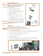
Figure 6-2.
MAIL ANALYSIS KIT
Figure 6-3.
D110PKU OIL FILTER
Summary of Contents for D110PKU
Page 4: ......
Page 6: ...vi About This Manual ...
Page 13: ...5 2 SPECIFICATIONS TOPICS IN THIS SECTION Technical Data 6 Dimensions 7 ...
Page 16: ...8 Specifications ...
Page 44: ...36 Troubleshooting ...
Page 48: ...40 Parts Catalog 8 6 ENGINE ASSEMBLY ...
Page 50: ...42 Parts Catalog 8 7 ENGINE MOUNTING ASSEMBLY ...
Page 52: ...44 Parts Catalog 8 8 ENGINE TO FRAME ASSEMBLY ...
Page 54: ...46 Parts Catalog 8 9 BATTERY ASSEMBLY ...
Page 56: ...48 Parts Catalog 8 10 EXHAUST ASSEMBLY ...
Page 58: ...50 Parts Catalog 8 11 COMPRESSOR ASSEMBLY ...
Page 60: ...52 Parts Catalog 8 12 INLET VALVE ASSEMBLY ...
Page 62: ...54 Parts Catalog 8 13 AIR FILTER ASSEMBLY ...
Page 64: ...56 Parts Catalog 8 14 RECEIVER ASSEMBLY ...
Page 66: ...58 Parts Catalog 8 15 RECEIVER ASSEMBLY TO FRAME ...
Page 68: ...60 Parts Catalog 8 16 CONTROL TUBING ASSEMBLY ...
Page 70: ...62 Parts Catalog 8 17 COOLING ASSEMBLY ...
Page 72: ...64 Parts Catalog 8 18 COOLING ASSEMBLY ATTACHMENT TO FRAME ...
Page 74: ...66 Parts Catalog 8 19 COOLING SYSTEM HOSES AND RECOVERY TANK INSTALLATION ...
Page 76: ...68 Parts Catalog 8 20 OIL FILTER AND DISCHARGE HOSE ASSEMBLY ...
Page 78: ...70 Parts Catalog 8 21 FUEL TANK ASSEMBLY ...
Page 80: ...72 Parts Catalog 8 22 INSTRUMENT PANEL ASSEMBLY ...
Page 82: ...74 Parts Catalog 8 23 CANOPY ASSEMBLY ...
Page 84: ...76 Parts Catalog 8 24 CANOPY INSTALLATION ...
Page 86: ...78 Parts Catalog 8 25 LIFTING BAIL ASSEMBLY ...
Page 88: ...80 Parts Catalog 8 26 FRONT CROSSMEMBER ASSEMBLY ...
Page 90: ...82 Parts Catalog 8 27 LIGHT PACKAGE ...
Page 92: ...84 Parts Catalog 8 28 FENDER INSTALLATION ...
Page 94: ...86 Parts Catalog 8 29 AXLE AND WHEEL ASSEMBLY ...
Page 98: ...NOTES ...
Page 99: ...NOTES ...


