28
MAINTENANCE
6.6
AIR/OIL SEPARATOR
Replace the air/oil separator every 600 hours or annually.
CAUTION!
Make sure to stop the engine before changing the oil
separator element. Let the engine cool down
sufficiently
–
oil can be hot and cause burns.
6.6.1 REMOVAL
1.
Relieve sump pressure to zero pressure.
2.
Loosen 8 screws on the separator lid.
3.
Remove the lid carefully so not to damage the
components and the dip tube attached to the cover.
6.6.2 INSTALLATION
1.
Apply a thin layer of oil on the seals of the new
element.
2.
Replace the oil separator element and flush.
3.
Screw 8 lid screws by hand and make sure to fasten
the air filter bracket.
4.
When the lid comes into contact with the surface of
the gasket, tighten the screws with a torque wrench
in order to avoid damaging the seals of the element.
NOTE!
Keep the separator oil level at maximum. The maximum
level is determined by the filling hole, so it cannot be
overfilled (See Fig. 6-4).
6.7
AIR FILTER
Check daily, every 10 hours of operation or on rent return.
Replace every 200 hours, or more frequently in dusty conditions.
CAUTION!
Since the air cleaner used on this engine is a dry type, never apply oil to it.
6.7.1 CLEANING AND REMOVAL
1.
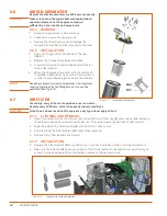
Open the evacuator valve (not shown), located on bottom of Filter Cap (
3
) once a week under ordinary
conditions, or daily when used in a dusty location. This will remove large particles of dust and dirt.
2.
Wipe the inside of Air Filter housing (
1
) with cloth if it is dirty or wet.
3.
Avoid touching the Filter Element (
2
) except when replacing.
4.
Remove dirty Filter Element and discard.
6.7.2 INSTALLATION
1.
Replace the Filter Element (
2
) every 200 hours, or sooner if working in dirty or dusty environments.
2.
Make sure the Filter Cap (
3
) is properly closed. If the filter envelope is not sealed, dust and dirt may be
sucked in, reducing engine life, and resulting in engine or compressor failure.
Figure 6-4.
D110PKU OIL SEPARATOR
Figure 6-5.
D110PKU AIR FILTER REPLACEMENT
Summary of Contents for D110PKU
Page 4: ......
Page 6: ...vi About This Manual ...
Page 13: ...5 2 SPECIFICATIONS TOPICS IN THIS SECTION Technical Data 6 Dimensions 7 ...
Page 16: ...8 Specifications ...
Page 44: ...36 Troubleshooting ...
Page 48: ...40 Parts Catalog 8 6 ENGINE ASSEMBLY ...
Page 50: ...42 Parts Catalog 8 7 ENGINE MOUNTING ASSEMBLY ...
Page 52: ...44 Parts Catalog 8 8 ENGINE TO FRAME ASSEMBLY ...
Page 54: ...46 Parts Catalog 8 9 BATTERY ASSEMBLY ...
Page 56: ...48 Parts Catalog 8 10 EXHAUST ASSEMBLY ...
Page 58: ...50 Parts Catalog 8 11 COMPRESSOR ASSEMBLY ...
Page 60: ...52 Parts Catalog 8 12 INLET VALVE ASSEMBLY ...
Page 62: ...54 Parts Catalog 8 13 AIR FILTER ASSEMBLY ...
Page 64: ...56 Parts Catalog 8 14 RECEIVER ASSEMBLY ...
Page 66: ...58 Parts Catalog 8 15 RECEIVER ASSEMBLY TO FRAME ...
Page 68: ...60 Parts Catalog 8 16 CONTROL TUBING ASSEMBLY ...
Page 70: ...62 Parts Catalog 8 17 COOLING ASSEMBLY ...
Page 72: ...64 Parts Catalog 8 18 COOLING ASSEMBLY ATTACHMENT TO FRAME ...
Page 74: ...66 Parts Catalog 8 19 COOLING SYSTEM HOSES AND RECOVERY TANK INSTALLATION ...
Page 76: ...68 Parts Catalog 8 20 OIL FILTER AND DISCHARGE HOSE ASSEMBLY ...
Page 78: ...70 Parts Catalog 8 21 FUEL TANK ASSEMBLY ...
Page 80: ...72 Parts Catalog 8 22 INSTRUMENT PANEL ASSEMBLY ...
Page 82: ...74 Parts Catalog 8 23 CANOPY ASSEMBLY ...
Page 84: ...76 Parts Catalog 8 24 CANOPY INSTALLATION ...
Page 86: ...78 Parts Catalog 8 25 LIFTING BAIL ASSEMBLY ...
Page 88: ...80 Parts Catalog 8 26 FRONT CROSSMEMBER ASSEMBLY ...
Page 90: ...82 Parts Catalog 8 27 LIGHT PACKAGE ...
Page 92: ...84 Parts Catalog 8 28 FENDER INSTALLATION ...
Page 94: ...86 Parts Catalog 8 29 AXLE AND WHEEL ASSEMBLY ...
Page 98: ...NOTES ...
Page 99: ...NOTES ...


