18
CoMPoNENT DESCRIPTIoN
3.5.3
OIL FILTER
A full-flow canister-style oil filter is supplied to protect the compressor unit from solid contaminants. The
filter has an internal bypass valve to assure adequate oil flow with cold oil or a plugged oil filter element. The
filter canister can be removed with a strap wrench.
3.6
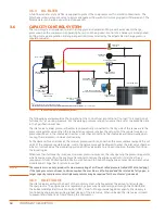
CAPACITY CONTROL SYSTEM
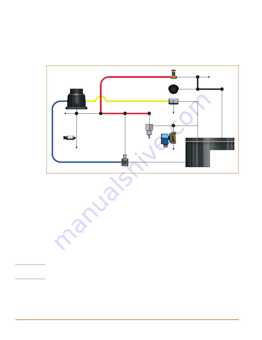
The control system is designed to match air supply to air demand and to prevent excessive discharge
pressure when the compressor is operating but air is not being used. Control of air delivery is accomplished
both by inlet valve regulation and engine speed control as directed by the adjustable discharge pressure
regulator valve(s).
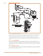
VENT DOWN TO
ATMOSPHERE
VENT DOWN TO
ATMOSPHERE
VENT DOWN TO
ATMOSPHERE
START/RUN
VALVE
PRESSURE
GAUGE
BLOWDOWN VALVE
INLET VALVE
RECEIVER TANK
VENT DOWN TO
ATMOSPHERE
COLD START SOLENOID
(OPTIONAL ON SOME MODELS)
PRESSURE
REGULATOR
NOTE:
1. SOLID PIPE CONNECTIONS REPRESENTED BY THIN LINES.
2. UNLESS SPECIFICALLY NOTED, INDIVIDUAL PART ORIENTATIONS ARE FOUND ON ASSEMBLY DRAWINGS
3. UNLESS SPECIFICALLY NOTED, IMAGES OF PARTS ARE FOR REPRESENTATION ONLY, ACTUAL PARTS MAY VARY IN APPEARANCE.
PRESSURE
SENDER/ THROTTLE
CONTROL
CD 00027
RECIRCULATION
VALVE
Figure 3-3.
CD 00027 CONTROL DIAGRAM D260U (REV 00)
The following overview explains the operation of the control from a condition of “no load” to a condition of
“full capacity” at working pressure. For the working pressure range of your machine, refer to applicable data
in the Specifications section.
The inlet valve cylinder pressure chamber is pneumatically connected to the dry side of the receiver via the
pressure regulator valve. When the receiver tank pressure is below the set point of the regulator valve no
pressure will exist in the inlet valve chamber. under these conditions, the inlet valve will remain wide open,
causing the compressor to deliver full capacity.
as the demand for air decreases, the receiver pressure will rise, and when this pressure level exceeds the set
point of the pressure regulator valve, control signal pressure will be allowed to enter the inlet valve chamber,
which in turn will move the modulating piston and the valve plate to a closed condition, thereby throttling
the incoming air.
When less than full capacity is required, receiver pressure increases, thereby opening the pressure regulator,
which allows a signal from the pressure transducer to reduce the engine speed until it matches the air
requirements from 100% down to 60%. From 60% down to 0% both engine speed reduction and inlet valve
modulation act together to reduce air output.
NOTE!
The compressor can only produce its maximum rating of air flow at rated pressure (rated CFM at rated psig).
If the tank pressure continues to decrease when the machine is at full speed and the inlet valve fully open, a
larger capacity compressor or multiple compressors may be required for the customer’s job needs.
3.6.1
INLET VALVE
The inlet valve assembly is the heart of the control system, which regulates the amount of air entering
the compressor. The engine speed is regulated by a pressure transducer signal through the
CANBUS
and
the Sullivan-Palatek Electronic Controller (SPEC).
From full to approximately 60% capacity, the delivery is
controlled by engine speed and a gradual closing of the inlet valve. When unloaded the inlet valve is closed
to prevent atmospheric air from entering the compressor.
Summary of Contents for D260UJD4PTOW
Page 4: ......
Page 6: ...vi About This Manual ...
Page 14: ...6 Safety ...
Page 21: ...13 Specifications 2 6 PTO SAE A DRIVE Figure 2 5 Power Take Off Auxiliary Drive Specs ...
Page 22: ...14 Specifications ...
Page 32: ...24 Component Description ...
Page 44: ...36 Installation and Operation ...
Page 58: ...50 Troubleshooting ...
Page 125: ...117 Parts Catalog ...
Page 134: ...NOTES ...
Page 135: ...NOTES ...

