19
CoMPoNENT DESCRIPTIoN
3.6.2
STArT-ruN VALVe
The start-run valve is used to bypass the compressor pressure regulator valve. This results in reduced
engine load at start-up. once the engine is warmed up, the valve can be moved to the RuN position. In the
STaRT position, the start-run valve is open. In the RuN position, it is closed.
3.6.3
reguLATOr VALVe (DiSCHArge PreSSure)
The regulator valve is used to select the desired discharge pressure within the operating pressure range.
Turning the regulator adjustment screw clockwise increases the unloaded pressure, and counter-clockwise
reduces the unloaded pressure. observe discharge pressure gauge on the instrument panel for compressor
discharge pressure. See
5.16 Control Adjustments on page 44
for more information
.
3.6.4
AUTOMATIC BLOWDOWN VALVE
The automatic blowdown valve relieves pressure in the system upon shutdown. It is closed when the
compressor is in operation; however, at shutdown, the inlet valve closes, the unit becomes pressurized and
sends a pressure signal to open the normally closed blowdown valve.
3.6.5
RECIRCULATION VALVE
This valve functions automatically in response to the regulated control pressure. Receiving the unload signal
to the inlet valve, the recirculation valve is opened allowing a small quantity of pressurized sump air to be
recirculated through the compressor in order to hold a positive pressure signal on the inlet side of the air
end to prolong the shaft seal life.
3.7
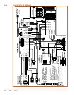
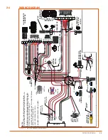
ELECTRICAL AND PROTECTIVE CIRCUIT SYSTEM
The compressor electrical system is a 12-volt negative ground system used on smaller-capacity (185–375
CFM) compressors and a 24-volt negative ground system used on larger-capacity (750–1800 CFM)
compressors. It is equipped with a protective circuit to minimize damage. Damage could be caused by high
compressor discharge temperature, high engine water temperature, or low engine oil pressure. Refer to
wiring diagrams as required. The following conditions will cause automatic shutdown of the compressor:
»
Compressor discharge temperature (CDT) of approximately 265°F (129°C). A warning is shown will ocur
when the temperature reaches 245°F (118°C).
»
low engine oil pressure (EoP) dependent upon engine manufacturer’s specifications.
»
low fuel (lF) warning at approximately 11% of the fuel tank. low Fuel (lF) shutdown will occur at
5 to 8%.
»
Coolant temperature exceeds 225°F (107°C).
3.8
NOISE CONTROL SYSTEMS
Noise control systems incorporated in this compressor have been designed to meet the requirements
of federal noise control regulations. The principal components of the noise control systems include the
enclosure, engine exhaust system, and compressor intake system. The enclosure has been designed to
provide the required noise reduction while maintaining a good distribution of cooling airflow to the radiator
and oil cooler.
3.9
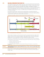
ENGINE SHUTDOWN PROTECTION
Sullivan-Palatek uses electronically controlled engines in the 185–1800 CFM line of compressors. Personnel
operating and maintaining these compressors MUST be familiar with and understand the operation and
protection features available with these engines.
WARNING!
Failure to follow the electronic control warnings and attempts to override, bypass, or ignore these
warnings can lead to severe engine damage. This damage will not be covered by either the engine
manufacturer’s or Sullivan-Palatek’s warranty.
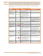
Electronically controlled engines have software that monitors engine parameters during operation. If the
parameters exceed the normal operating threshold, the engine software will take appropriate actions to
protect the engine from damage. There are two levels of action: derate and shutdown. If either of these
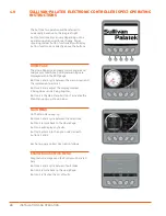
actions are initiated, the software will also activate the yellow warning sign and red engine shutdown/
diagnostic warning sign on the Sullivan-Palatek Electronic Controller (SPEC).
3.9.1
ENGINE DERATE
The first level of protection in the controller is the derate feature. The engine will derate the power output
of the engine by 35% in an attempt to correct the parameters that are out of range. In almost every case,
power deration will result in the engine stalling, which will protect the engine from damage.
NOTE!
The yellow warning will be lit on the SPEC screen when this occurs.
Summary of Contents for D260UJD4PTOW
Page 4: ......
Page 6: ...vi About This Manual ...
Page 14: ...6 Safety ...
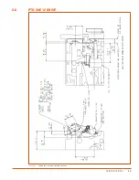
Page 21: ...13 Specifications 2 6 PTO SAE A DRIVE Figure 2 5 Power Take Off Auxiliary Drive Specs ...
Page 22: ...14 Specifications ...
Page 32: ...24 Component Description ...
Page 44: ...36 Installation and Operation ...
Page 58: ...50 Troubleshooting ...
Page 125: ...117 Parts Catalog ...
Page 134: ...NOTES ...
Page 135: ...NOTES ...

